


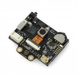

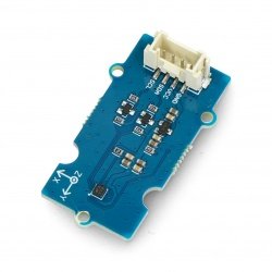


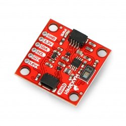
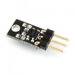
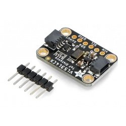


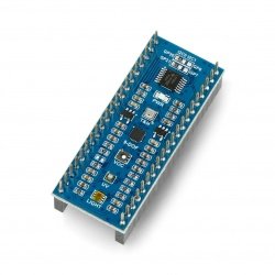


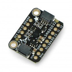


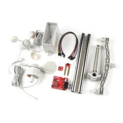


MinImu-9 v2 and Arduino
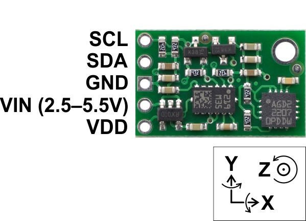
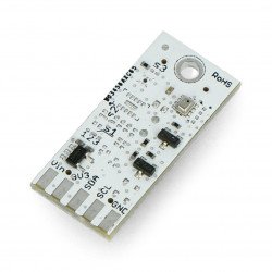
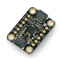
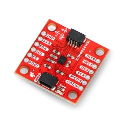
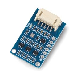
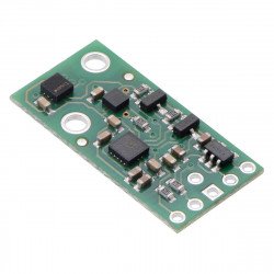
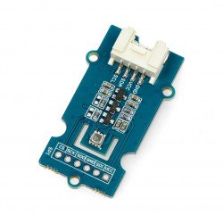
It is a module containing a -3-axis accelerometer 3-axis magnetometer(LSM303DLHC) and 3-axis gyroscope(L3GD20). Apart from the sensors themselves, the board contains the necessary passive components such as capacitors, resistors, transistors and voltage regulators. Thanks to this, the user does not have to worry about the design of the PCB and the proper arrangement of elements. The circuit has five leads. Three of them are used for power supply, the other two are I2C (SDA - data line, SCL - clock line).
I2C/TWI bus
An interest consisting of a data line (SDA) clock line (SCL) and mass. The outputs/inputs are in Open-Drain (Open-Collector) configuration, therefore pull-up resistors are required.

Fig: Example of I2C bus structure. (source: http://www.eetimes.com)
Transmission can be carried out in three modes:
- Normal Mode - transmission speed up to 100 kbps, 7-bit addressing
- Fast Mode - transmission speed of up to 400 kbps, 7 or 10-bit of the recipient
- High Speed Mode - transmission speed up to 3.4 Mbps, 7 or 10-bit of the recipient
Since the Fast Mode version, devices can be addressed in 10-bit and 7-bit mode (up to 128 devices, in practice a little less - 112 addresses are reserved). The accelerometer, magnetometer and gyroscope, located in MinImu-9 module, have 7-bit addresses. They are set to the following addresses:
- Accelerometer LSM303DLHC- 0011001b
- Magnetometer L3GD20- 0011110b
- Gyroscope L3GD20- 1101011b (with the possibility of configuring the last bit with a jumper)
For detailed information on I2C bus, see NXP documentation: link.
To connect MinImu9 to Arduino just connect the power supply and I2C/TWI outputs:
| MinImu9 | Arduino | Description |
| SCL | SCL | I2C/TWI bus clock line |
| SDA | SDA | I2C/TWI bus data line |
| GND | GND | The mass of both systems must be combined |
| VIN | 3.3V or 5V | Power to the system. MinImu9 has its own regulator with 3V output voltage. It does not matter whether 3,3V or 5V is connected. Connecting 3.3V will eliminate the power loss in the form of heat emitted on the stabilizer. |
| VDD | - | This is the output voltage from the 3V stabiliser on the MinImu9 board with a maximum current capacity of 150mA. The output can be used when the supply voltage (given on the VIN pin) is higher than 3.3V. |
Attention!
MinImu-9 has pull-up resistors (4.7k ohm) for both I2C lines (for accelerometer and gyroscope). The resistors on Arduino side should be taken care of.
Similarly, the L3GD20 gyroscopeand accelerometer with magnetometer LSM303DLHC should be handled .
Libraries and sample programs
There were created libraries for Arduino to operate the module. Library for L3GD20 digital gyroscope module and accelerometer with LSM303 magnetometer.
The manufacturer also provides a sample program for Arduino project.
The video shows a 3D model controlled in real time by means of: MinImu-9, Arduino and 3DSMax.