


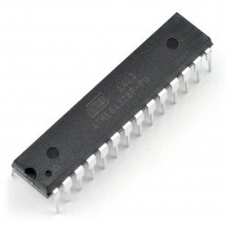
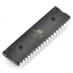


Example of power connection for ATmega8A microcontroller from ATmel AVR family.

The reset in the AVR microcontrollers is internally pulled up to VCC. However, the manufacturer recommends that an external pull-up resistor be inserted in the technical note if the system operates in an environment that is subject to interference. We recommend adding an external 10k Ohm resistor.
The analog/digital converter has separate power pins. The manufacturer recommends connecting separate power supply lines (through a 10uH choke) and ground (analog and digital ground should connect at one point of the PCB) in order to reduce interference. This will allow for higher accuracy of the transmitter. If the maximum resolution offered by Atmel (10bit) is not needed, we do not need to run separate tracks. The AREF pin is the reference voltage for the transmitter. AVRs give you the possibility to choose an internal reference voltage source. If we decide to do so, the AREF should be connected through a 100nF capacitor to ground. The choke and capacitors form an LC filter. If you do not use these elements you will also lose the A/C accuracy. Attention! Even if the transmitter will not be used, the AVCC and AGND pins should be connected because they are also the power supply for PORTC.
The maximum clock frequency of this microcontroller is 16MHz. The values of capacitors are given by the manufacturer in the documentation. In the example for 16MHz quartz we used 22pF.
4. power supply. For each VCC-GND pair the manufacturer recommends 100nF capacitor. It is also recommended to use a choke. However, from practice we know that AVRs work well without this element. Of course, everything depends on the environment in which they work. If there is space on the PCB it is worth to use this choke, as recommended.
The ISP (In-System Programming) connector allows to program the microcontroller in the target circuit. It uses SPI interface.