
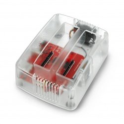


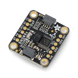


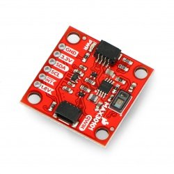


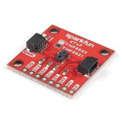


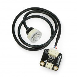


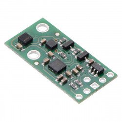
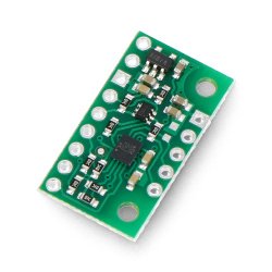


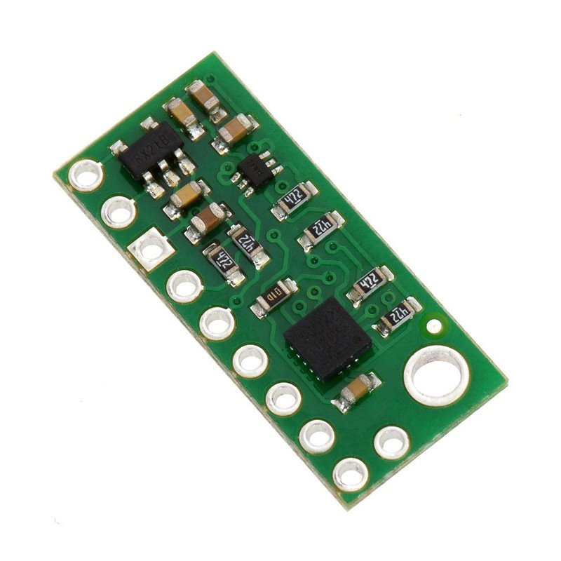


Sensor to measure the angular velocity in three axes. It works in the range of up to ±240 °/s, ±500 °/s or ±2000 °/sec. It communicates via the I2C or SPI bus, it has the voltage regulator, it is powered with the voltage from 2.5 V to 5 V.
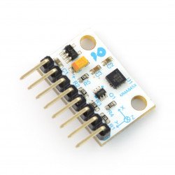
The module is equipped with gyroscope L3GD20H which is used to measure the angular velocity in three axes X, Y, Z. It has the possibility to choose the measuring range from available: ±245 °/s, ±500 °/s or ±2000 °/s. Ease of use is provided by a built-in LDO regulator, thanks to which, the system can be powered with any voltage from 2.5 to 5.5 V. In practice, this means that it works with 3.3 V systems (e.g.Raspberry Pi) and 5 V (for example,Arduino UnoandLeonardo).
|
The product is compatible with Arduino Manufacturer has prepareda library on GitHub which simplifies the use of the module for the users ofArduino. |
In the L3GD20H, therw was introduced many improvements in relation to earlier version - the L3GD20, the most important ones are: higher measurement accuracy, lower current consumption and reduced start time. Sensor L3GD20H is equipped with a pin DEN which allows to synchronize the read of data with an external device. Both systems have the same address of the I2C bus, so code written for a previous version of L3GD20, will work also with the new L3GD20H.

The gyroscope has lots of configuration options, including the possibility to choose: the sensitivity of the angular velocity at seven different transmission speeds, seven modes of the FIFO buffer. The user can also set the external interrupt and select the communication interface - I2C or SPI.
The sensor has ten pins for mounting the goldpinconnectors - pitch of 2.54 mm(included).


| PIN | Description |
|---|---|
| VIN | Supply voltage: 2.5 V - 5.5 V. The voltage converter sets the high status of SCL and SDA pins to this value. |
| GND | The potential of the ground of the system. |
| VDD | Regulator's output of 3.3 V with a maximum performance of 150 mA. |
| SCL/SPC | Clock I2C/SPI line connected via voltage converter. High status is equal to VIN voltage, low status is 0 V. |
| SDA/SDI | Input data line of I2C / SPI connected via voltage converter. High status is equal to VIN, low is 0 V. |
| SDO | Input data SPI line is also used to change the address of the I2C bus.This pinn has no voltage regulator, it tolerates only a voltage of 3.3 V. |
| CS | Pin to enable the SPI bus by indicating the low status. By default, it is pulled up to 3.3 V - enabled I2C interface.This conclusion has no voltage regulator, it tolerates only a voltage of 3.3 V. |
| DRDY/INT2 | Data availability to read / interrupt for the FIFO queue.This pin has no voltage regulator, it tolerates only a voltage of 3.3 V. |
| INT1 | Customable interrupt.This pin has no voltage regulator, it tolerates only a voltage of 3.3 V. |
| DEN | Release of measurement data.This pin has no voltage regulator, it tolerates only a voltage of 3.3 V. |
The choice of communication interface is performed by setting the appropriate logic status at the pin CS, which is internally pulled up to 3.3 V. This means that by default, the system communicates via the I2C bus. To select the SPI option, the CS pin must be shorted to ground.
The system has a 7-bit address, the last bit (LSB) of which is configured via the SDO pin. By default, the SDO is pulled up to VCC via 4.7 kΩresistor which set the address to 1101011b. If there is a conflict with another device, you can change the address by connecting the SDO to the masses. It will change the last bit of LSB to 0. The details of the transmission and a description of the registers is inthe system documentation.
The manufacturer indicates that the system works flawlessly for a frequency of 400 kHz (I2C fast mode). Above this value, the interferences may occur in the transmission.
To choose the connection via the SPI, CS pin must be connected to ground, and, after transmission, set again a high status on it. Detailed description of the transmission and the contents of the configuration register is inthe system documentation.
Here's some information you should know before connecting the sensor:
Useful links |
| Package width | 7.5 cm |
| Package height | 8.5 cm |
| Package depth | 0.1 cm |
| Package weight | 0.003 kg |
Be the first to ask a question about this product!


