


- EOL

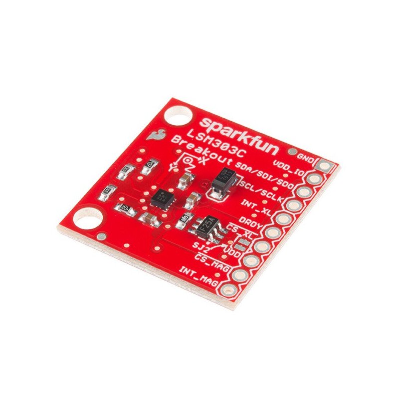


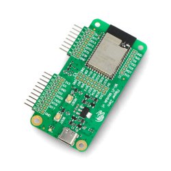
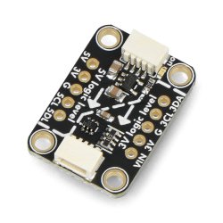
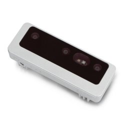
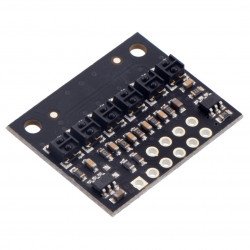
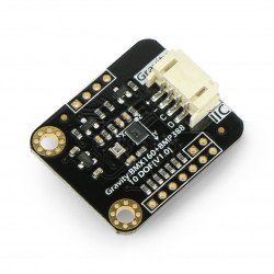
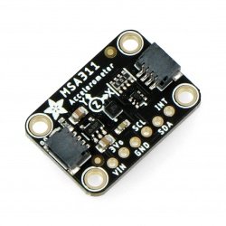
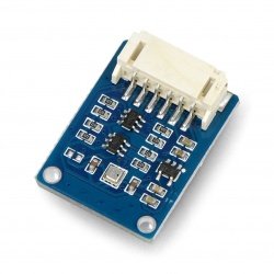
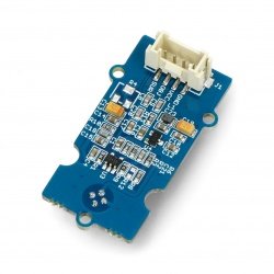
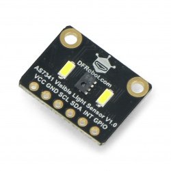
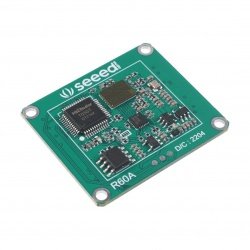
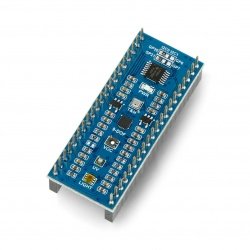
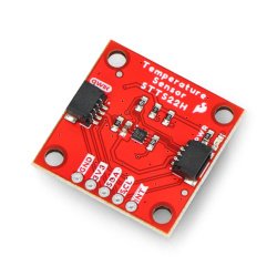
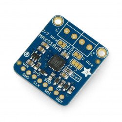
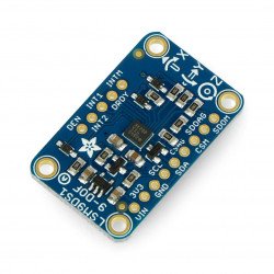
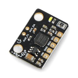
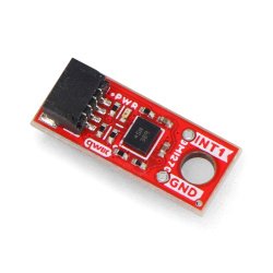
The sensor is a combination of a 3-axis digital accelerometer and a compass. It allows to measure acceleration and magnetic field in configurable ranges. It communicates via the I2C or SPI bus and is powered from 1.9 V to 3.6 V.
|
Attention! The product has been discontinued. Check other products in category. |
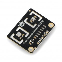
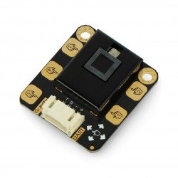
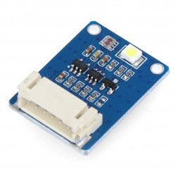
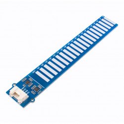
The MEMS module allows the measurement of acceleration and magnetic field in three axes of three-dimensional space. The device is a combination of a digital accelerometer and magnetometer, communicating via the SPI or I2C bus. In addition, it has a built-in temperature sensor, an integrated FIFO buffer and programmable interrupts, which allow, among other things, for free fall detection.
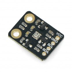
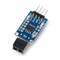
For communication with the central unit, the user can select the SPI or I2C interface. The module has the necessary passive elements for proper operation of the system. The leads are holes to solder thegoldpin connectors(not included in the set), which allow the sensor to be connected bywires ordirectly connected to the contact plate.
Details on the technical parameters of the sensors can be found in the documentation.

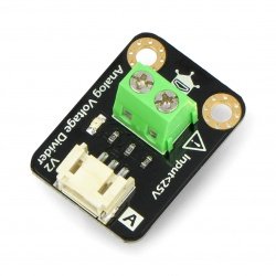
Since the maximum voltage with which the system operates is 3.3 V, a voltage converter is required to work with Arduino. The exception are modules working with 3.3V e.g. ArduinoPro Mini 328 - 3.3V/8MHz.
|
Product compatible with Arduino In order to facilitate work with the module, the manufacturer has prepared auser guidewith a sample program for Arduino and project files with a library available onGitHub. |
The sensor has leadings for mountinggoldpin-typeconnectors- 2.54 mm raster(not included in the set, must be purchased separately and soldered separately).
| Pin |
Description |
|---|---|
| VDD_IO |
Supply voltage of the I/O pins of the system from 1.71 to VDD. |
| GND | The weight of the system. |
|
SDA SDI SDO |
|
|
SCL SCLK |
I2C bus clock line (TWI) and SPI. |
| INT_XL |
Accelerometer interruption output i - (seedocumentationfor details). |
| DRDY |
Breaking the akacelerometer informing that new magnetometer data is readable. |
| CS_XL |
Choice of communication interface of the accelerometer:
|
| CS_MAG |
Selection of the communication interface of the magnetometer:
|
| VDD | Supply voltage from 1.9 V to 3.6 V. |
| INT_MAG | Programmable magnetometer interrupt output - (details inthe documentation). |
Useful links |
| Package width | 3.5 cm |
| Package height | 0.4 cm |
| Package depth | 3.5 cm |
| Package weight | 0.003 kg |
Be the first to ask a question about this product!


