


- EOL

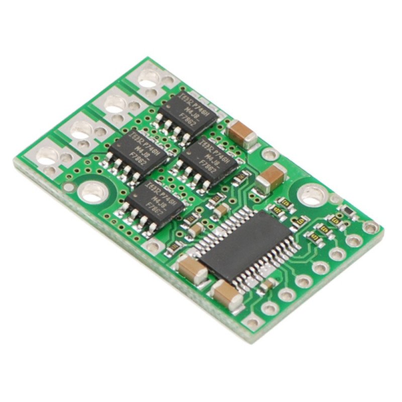


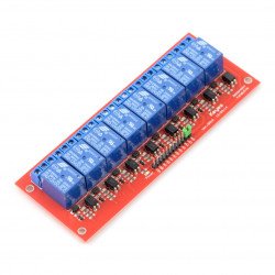
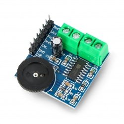
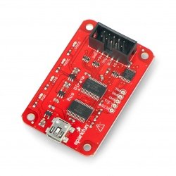
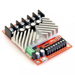
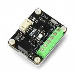
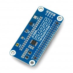
Based on MOSFET transistors, the powerful H-bridge allows you to control the motor rotation in both directions. Motor power supply: 5.5 V to 40 V. Maximum current: 12 A.
|
Attention! The sale of the product has been completed. Check others in thiscategory. |
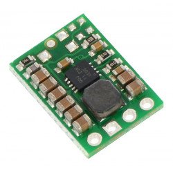
A controller based on MOSFET transistors allows you to control one DC motor supplied with a voltage from 5.5 V to 40 V with a current consumption of up to 12 A.
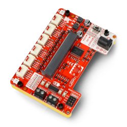
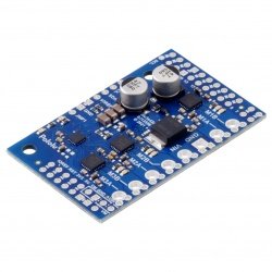
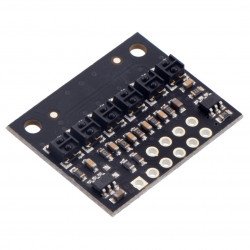
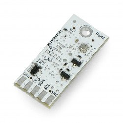
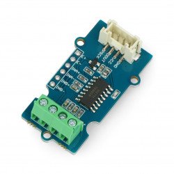
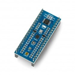
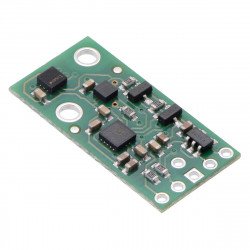
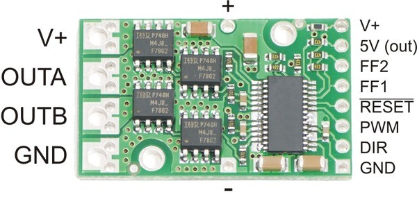
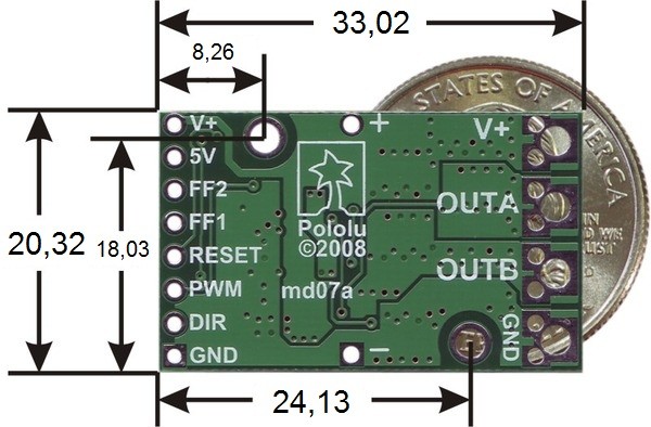
The outputs are located on both sides of the module. One of them is equipped with connectors responsible for controlling and powering the logical part. On the opposite edge are the power supply pins for the motor (V+, GND) and its outputs (OUTA, OUTB). The voltage value of control signals should be in the range from 3.5 V to 5.5 V. The manufacturer does not recommend working on 3.3 V.
In standard application it is required to connect the PWM signal and the DIR motor direction selection pin. Flags FF1 and FF2 signal incorrect operation. The RESET pin is pulled to the power supply by default. When the low state is reached, the system will switch to the minimum power consumption state. All flags will also be reset.
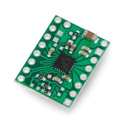
A system based on a MOSFET transistor with an NIRF7842PbFwith a channel resistance of 5 mΩ. Details in thedocumentation.
| PIN | Description |
| V+ | Motor power supply (5.5 V to 30 V). The output marked with + is the positive pole of the capacitor connection. The smaller V+ outputs allow you to monitor the motor power supply. Use for high currents is not recommended. |
| 5V (out) | 5 V voltage stabilizer output. Output current up to several mA. Be careful not to short-circuit the adjacent V+ pin as this leads to irreparable damage to the module. |
| GND | The mass potential of the system. |
|
OUTA OUTB |
DC motor outputs. |
| PWM | Speed control signal. Default is in a low state |
| DIR | Selection of the direction of engine rotation. In high state current flows from OUTA to OUTB. By default in float state. |
| RESET | When low state is given, the system is in low power state. It also deletes all flags. |
|
FF1 FF2 |
System state flags. In case of an error, a high state appears. |
| FF1 | FF2 | Description | Blocked the exits? |
| L | L | No mistakes | NO |
| L | H | Shortcut | YES |
| H | L | Too high a temperature | NO |
|
H |
H |
Too low a voltage | YES |
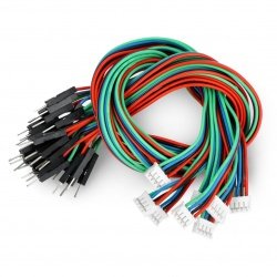
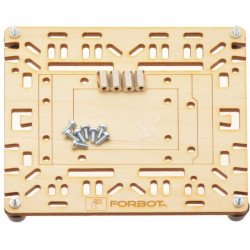
The module contains: printed circuit board with installed circuits, leads and capacitor to be soldered.
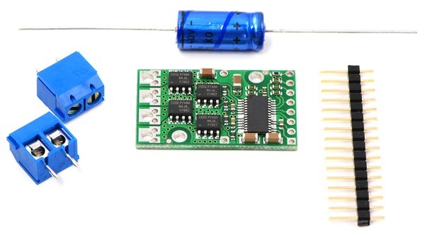
Set contents.
Useful links |
| Voltage to | 5.5 V |
| Voltage from | 40.0 V |
| Current | 12.0 A |
| Channels | 1 |
| Package width | 0.001 cm |
| Package height | 0.001 cm |
| Package depth | 0.001 cm |
| Package weight | 0.001 kg |
Be the first to ask a question about this product!


