Table of Contents:
Transistors are some of the most important semiconductor devices used in electronics – they are the basis for the internal structures of most integrated circuits.
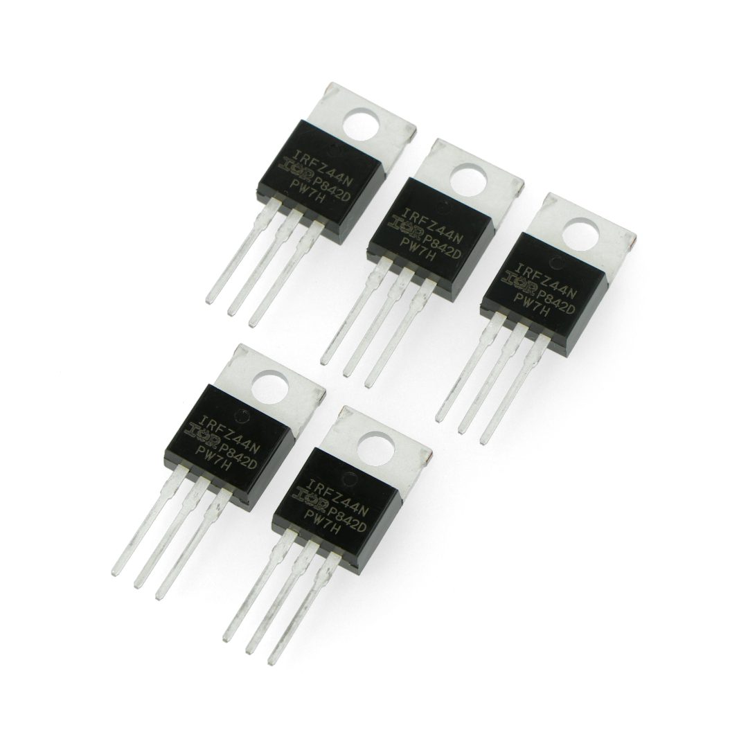
However, in addition to integrated circuits, transistors also exist in single form, as discrete components – meet the IRFZ44N – a single N-channel MOSFET transistor.
What is and how does the IRFZ44N transistor work?
The IRFZ44N is a Metal Oxide Semiconductor Field Effect Transistor ( MOSFET ), also known as a unipolar transistor because its semiconductor structure involves a single type of carrier, i.e.
N-type or P-type. In the case of the IRFZ44N transistor, we are dealing with an N-type channel, where the majority carriers are electrons, on the contrary to P-type MOSFET transistors, where the majority carriers are holes.
In an N-type MOSFET transistor, none of the minority carriers participate in the current conduction.
Therefore, the electrical charge storage time after switching off is negligibly short, and thus MOSFET transistors are successfully used in electronic circuits with high switching frequencies.
A MOSFET with an N-type channel is turned on when the gate-source voltage VGS is positive with respect to ground.
In power electronic circuits, MOSFET transistors act as fast switches.
The VGS voltage must be within the lower and upper limits specified in the catalog note.
When a MOSFET is in the conducting state, it behaves similarly to a resistor.
Thus, the power loss in such a transistor is proportional to the square of the drain current and the resistance between the drain and the source in the transistor’s on state.
The value of this resistance increases with the drain current due to the increase in junction temperature.
This results in increased power loss during conduction, and thus limits the application in high-power circuits.
Low-voltage MOSFET transistors have low on-state resistance, so for given voltage requirements it is better to choose power MOSFETs with the minimum possible voltage rating, taking into account the safety factor.
Example application of IRFZ44N MOSFET - acoustic alarm
A circuit break alarm can be reasonably associated with an acoustic alarm circuit, which is triggered by a break in the continuity of an electrical circuit.
Such an example circuit needs an auxiliary supply voltage in the range of 9-12 V for general operation.
The principle of operation of such a circuit, is as follows.
When the power supply is connected, current flows from the supply voltage potential Vcc to GND through a 33k resistor.
On the other hand, when this circuit is interrupted, the current will flow from Vcc potential to the gate of the MOSFET.
As a result, the MOSFET enters the conduction state – current flows from the drain to the source through the LED and buzzer.
Such a circuit can be used as an indication of discontinuity of electrical conductors, for example, as a result of damage due to the flow of too much current.
IRFZ44N - key parameters of the component
IRFZ44N is a popular N-type MOSFET transistor, often used in applications related to power regulation, motor control, switching power supplies, audio amplifiers and many others.
Among the most important parameters of this transistor are:
- Rated gate-to-source voltage (Vgs): Specifies the maximum voltage that can be safely applied between the gate and source for the transistor to function properly.
- Drain-to-source rated voltage (Vds): The maximum voltage that can be safely applied between the drain and source when the transistor is turned on.
- Drain current (Id): The maximum current that can flow through a MOSFET transistor when it is fully on.
- Conduction resistance (Rds(on)): Determines the resistance between the drain and the source when the transistor is fully on.
The lower the value, the lower the power loss and the better the performance. - Gate threshold voltage (Vth): The minimum voltage that must be applied to the gate in order for the transistor to start conducting current.
- Power rating (Pd): The maximum power that a MOSFET transistor can dissipate without exceeding allowable temperatures.
- Switching time (t-on, t-off): The time it takes for a MOSFET transistor to go from the off state (off) to the on state (on) and vice versa.
Fast switching times can be important in some applications, such as DC-DC converters. - Gate-to-source capacitance (Ciss): Capacitance between the gate and source that affects the switching speed of a transistor.
Testing the MOSFET transistor
Like other electronic components and elements, the MOSFET transistor is also a component that can be subject to damage.
For this purpose, in order to be sure that the transistor we want to use in our project is functional, it is worth testing it.
Interestingly, for this purpose we can use not only a multifunctional electronic component tester, but also a multimeter and a battery, or power supply.
Testing an N-type MOSFET transistor with a multimeter can be done in a few simple steps.
Set the multimeter to resistance measurement mode.
The resistance value can vary depending on the type of MOSFET, but it will usually be within a few hundred kilohms.
In the off state, apply the multimeter’s probes to the gate and source leads.
The multimeter should display an infinite value.
After briefly applying a voltage to the gate, conduction should appear between the source terminal and the drain.
The multimeter should show a low resistance.
To measure the gate-to-source voltage to determine the voltage characteristics of the MOSFET, we can measure the voltage between the gate (G) and the source (S), after applying a supply voltage to the source.
With the gate voltage correctly applied, the MOSFET should be fully conductive.
Next, we check the resistance from the source to the drain, which is a kind of “parallel resistor” of the MOSFET in the conducting state.
The value of this resistance should be relatively low, indicating that the MOSFET is in the conducting state.
If all the mentioned steps meet the mentioned assumptions, we can conclude that the tested MOSFET is operational.
How useful was this post?
Click on a star to rate it!
Average rating 5 / 5. Vote count: 1
No votes so far! Be the first to rate this post.