Table of Contents:
Although the roots of Class-D audio amplifier technology date back to the late 1950s.
The 1950s, there have been tremendous advances in this technology since then.
Class-D audio amplifiers are gaining more and more fans because of their improved efficiency and more careful design refinement to eliminate distortion – yet designing an audio amplifier, especially in Class-D, requires a very good understanding of the phenomena within it at the level of advanced mathematics and physics.
Class-D audio amplifier on MOSFET transistors
In this article, we will focus on the basic principle of a class-D audio amplifier, describing how to input signals, design comparators with the selection of auxiliary components, and highlight frequency filters and a power stage based on a complementary pair of IRF3205 and IRF4905 field-effect transistors.
The basic principle of a class-D audio amplifier
The Class-D audio amplifier, a simplified schematic of which is shown in Fig.
1, works by using a pulse width modulated (PWM) signal to switch transistors in the power stage at high frequency.
Such high-frequency switching results in an amplifier output that is proportionally amplified relative to the input signal.
The input signal fed into the amplifier is first converted into a PWM signal by a driver in the preamplifier stage and a high-speed comparator based on an operational amplifier.
The PWM signal is then used to drive the MOSFET transistors in the power stage (such as the aforementioned IRF3205 which is capable of fast turn-on and turn-off at high frequencies).
The output signal from the power transistors is then fed into LC high-pass filters to filter out the high-frequency switching signal, leaving only the useful audio signal we want to hear in the form of music, speech or sound effects at the output.
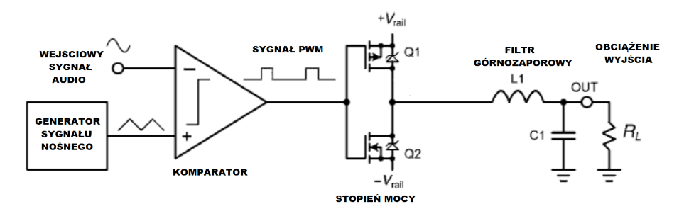
The basic principle of a class-D amplifier is as follows: A class-D power amplifier, works by modulating the audio input signal with a high-frequency carrier signal, which usually has a triangular waveform.
Then, the audio input signal is mixed with the high-frequency carrier signal using an operational amplifier, resulting in an audio signal in the form of a PWM waveform.
In this circuit, the operational amplifier is used as a differential comparator.
The useful audio signal is included in the PWM signal and it is routed to the gates of MOSFET transistors connected in a push-pull topology.
The positive parts of the PWM signal drive only the upper transistor (N-type channel), and the negative parts of the PWM signal drive only the lower transistor (P-type channel).
When the transistors are switched, there is a current-free break at their outputs, which is necessary to prevent short-circuiting between the power rails through the resistance of the drain-source channels of the transistors, so as not to damage them.
The use of high-frequency switching technology ensures high efficiency of the power stage even in the neighborhood of 90%, so that we have much lower power loss to heat and lower power consumption from the power source than class A or class AB audio amplifiers.
Class-D audio amplifiers are widely used in portable battery-powered audio devices (such as portable Bluetooth speakers), car audio systems, and other applications where efficiency and maintaining minimum geometric dimensions are key requirements.
PWM waveform generation
In a class-D audio amplifier, the PWM signal is produced by a specialized driver IC.
The driver, after feeding the input audio signal to the input by mixing it with a triangular signal, produces a high-frequency PWM signal at the output, which typically has a rectangular waveform with frequencies of hundreds of kHz to several MHz.
The fill factor of the PWM signal is proportional to the amplitude of the audio signal at the input, where a fill factor of 0% indicates a minimum (negative) signal value, 50% indicates a zero signal value, and a fill factor of 100% indicates a maximum signal value.
The driver IC is typically based on a comparator, which compares the input audio signal with a reference voltage, which typically has a triangular waveform.
The output of the comparator produces a PWM signal, which is then used to drive the transistors in the power stage.
Power stage overdrive and amplifier output filtering
The driver circuit in the input stage, is also equipped with a dead time generator that protects the transistors in the power stage from being turned on and off both at the same time, so as not to short circuit the output.
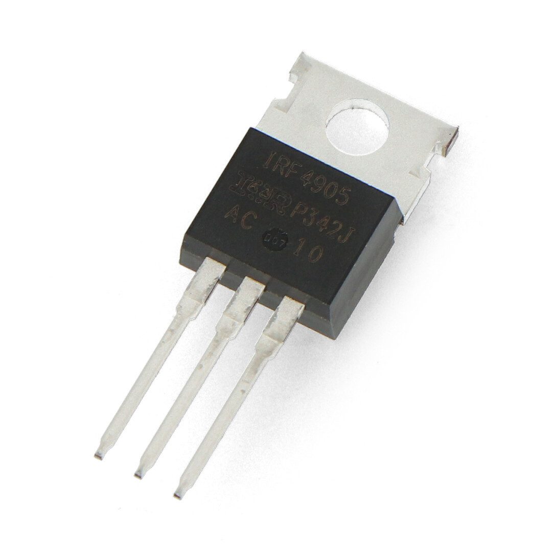
The power stage typically uses unipolar transistors (MOSFETs) connected as a complementary pair , such as IRF3205 (N-type channel) together with IRF4905 (P-type channel).
The PWM signal, after being amplified by the transistors, is further present at the output of the power stage, where it is fed further to an LC high-pass filter to remove high-frequency interference, leaving only a clean audio signal at the output of the filter which is then delivered to the speakers.
One of the most popular approaches in designing a filter between the power stage and the speakers, is to use a second-order Butterworth high-pass filter.
For the sake of long and reliable operation of the system, instead of electrolytic capacitors, it is recommended to use solid dielectric capacitors, such as metallized polyester (MKT/MKSE) or polypropylene (MKP).
In addition, such capacitors have very low equivalent series resistance (ESR) and are usually made with higher accuracy than electrolytic capacitors.
How useful was this post?
Click on a star to rate it!
Average rating 4.4 / 5. Vote count: 5
No votes so far! Be the first to rate this post.