Table of Contents:
In this article, we will focus on the MC34063 IC, which is typically used in DC voltage converter electronics for power supply in Boost or Buck topologies, among others, and design a DC voltage booster circuit from 5V to 12V based on this IC.
General characteristics of the MC34063 integrated circuit
The MC34063 IC is a DC/DC converter most commonly used in Buck topology converters for voltage reduction and Boost topology for voltage boost. The MC34063 IC contains all the necessary blocks to build DC voltage converters, and the range of switched frequencies supported by this IC reaches 100kHz. The MC34063 is popular in DC/DC converter circuits because of its voltage conversion capabilities and its low price and simple implementation.
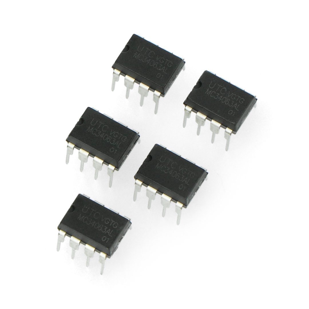
The operating temperature range of this IC reaches from 0*C to 70*C. The MC34063 is commonly used in voltage regulator circuits, chargers, and other electronic applications with non-standard power needs. The MC34063 chip can be purchased in an 8-pin DIP package for THT mounting, as well as in a SOIC package for SMD mounting.
Functions of the MC34063 integrated circuit
The MC34063 IC can perform the following functions:
- oscillator;
- Electronic switch with high current output capacity;
- peak current detector;
- A circuit that detects the presence of voltage at the output of the comparator;
- A thermally compensated reference voltage source.
Thanks to the detailed design of the individual blocks of the MC34063 chip, it requires a minimum number of peripheral components to implement the above and many other applications.
MC34063 - circuit pinout description
The MC34063 IC is housed in a housing manufactured in both SMD and THT versions. Eight leads can be found in both housings, and their functions are as follows:
- collector of the switching transistor
- collector of the switching transistor
- external capacitor of the inverter timing circuit
- circuit ground (GND)
- inverting comparator input setting the output voltage
- auxiliary power voltage input (VCC)
- load current detection
- collector of the output transistor of the inverter
Basic topologies of the MC34063 integrated circuit
The MC34063 IC has a wide range of input supply voltages, i.e. from 3V to 40V, and can deliver a switchable current of up to 1.5A at the output when a coil of suitable inductance is added. The chip allows output voltage regulation, short-circuit current limitation and low standby current consumption. With this IC, we can build a DC/DC converter in buck, boost and reverse voltage polarity topologies using several additional external components. DC/DC converters are often used to efficiently provide regulated voltages that can be properly controlled under varying loads. A Buck converter produces a voltage that is reduced relative to the input voltage, while a Boost converter produces a voltage that is increased relative to the input voltage.
Boost inverter
At the heart of the circuit is the switching regulator IC MC34063A. The 1N5819 Schottky diode has a low wire voltage drop and high switching speed. It is often used in high-frequency applications such as inverters and DC-DC converters. Because the MC34063A can withstand voltages up to 40 V, the circuit can handle DC voltages ranging from 3.0 V to 40.0 V. It offers adjustable output voltage, short-circuit current limitation and low standby current.
Now, at this stage, we will proceed to build our circuit and discuss the components that will be included in it, along with their respective values.
After reviewing the application note, we can get the full calculation formula needed to determine the desired values according to our requirements. In the datasheet, we will find calculation formulas that will help us identify the appropriate values.
Now we will perform the calculations of the values needed for our project, based on the formulas available in the datasheet.
Step 1:
First, we will choose a diode for the calculation. We will use the popular 1N5819 diode. According to the datasheet, at a conduction current of 1A, the diode’s conduction voltage will be 0.49V.
Step 2:
We will calculate Ton/Toff using the formula, where:
Vout = 12 V,
The conduction voltage of the diode (Vf) = 0.49 V,
Minimum Vin voltage (min) = 4.5 V,
Saturation voltage of the output switch (Vsat) = 0.45 V.
After substituting these values into the formula, we get:
(12 + 0,49 – 4,5) / (4,5 – 0,45) = 1,97
Hence Ton/Toff = 1.97
Step 3:
Now we will calculate Ton + Toff according to the formula:
Ton + Toff = 1 / f
Where the switching frequency is 50kHz, according to the application note.
Tone + Toff = 1 / 50 kHz = 20us
Step 4:
Next, we will calculate Toff:
Toff = (Ton + Toff) / (Ton/Toff + 1)
According to the previous calculations from step 2 and step 3:
Toff = 20 us / (1.97 + 1) = 6.73 us
Step 5:
We will calculate Ton:
Ton = (Ton + Toff) – Toff
Ton = 20 us – 6.73 us = 13.27 us
Step 6:
We will choose the value of capacitor Ct needed to achieve the desired frequency.
Ct = 4.0 x 10^-5 x Ton
Ct = 4.0 x 10^-5 x 13.27 us = 530.8 pF
There is a 560 pF capacitor available on the market that can be used.
Step 7:
We will calculate the peak current:
Ipk = 2 x Iout(max) x (Ton/Toff + 1)
The maximum output current is 200 mA.
Ipk = 2 x 0.2 A x (1.97 + 1) = 1.2 A
Step 8:
We will calculate the value of the sensing current resistor (Rsc):
Rsc = 0.3 / Ipk
Rsc = 0.3 / 1.2 A = 0.25R
Step 9:
We will calculate the minimum inductance of the coil(Lmin):
Lmin = ((Vin(min) – Vsat) / Ipk) x Ton(max)
Lmin = ((4.5 V – 0.45 V) / 1.2 A) x 13.27 us = 44.8 uH
Step 10:
We will calculate the value of the output capacitor (Cout):
Cout = 9 x (0.2 A x 13.27 us) / 0.2 V
Cout = 119.43 uF
We will use a 120 uF 20 V capacitor.
Step 11:
We will calculate the values of the feedback voltage resistors:
Vout = 1.25 x (1 + R2 / R1)
By setting Vout = 12 V
We will choose R1 = 910 ohms,
R2 = 8.2 kiloohm (8.6 x R1)
Now we have all the required values. All we have to do is build the circuit from the schematic and run it!
How useful was this post?
Click on a star to rate it!
Average rating 5 / 5. Vote count: 2
No votes so far! Be the first to rate this post.