Table of Contents:
Traditional mechanical gyroscopes were widely used in aviation and navigation before the introduction of electronic technologies.
These mechanical devices used the physical properties of a rotating solid to maintain a constant orientation in space.
Today, small and large electronics come to our aid.
Electronic gyroscope - what is it?
A gyroscope is also known as an inertial measurement unit (IMU).
It is an electronic device used to measure the angular velocity (rotational motion) and angular acceleration (change in angular velocity) of an object in space.
They take into account the principle of using the Coriolis effect in their operation.
Example: a sink with a drain allows you to observe how water behaves around the drain.
This movement is caused by the rotation of the Earth.
In the northern hemisphere, this water will “circulate” clockwise, and in the southern hemisphere in the other, which is precisely due to the Coriolis effect.
There are many classes of gyroscopes, depending on the physical principle of operation and the technology used.
Gyroscopes can be used independently or be part of more complex systems, such as the aforementioned inertial measurement units, gyrocompasses, navigation systems or course reference systems.
Today we are particularly interested in microelectromechanical system (MEMS) gyroscopes.
MEMS (Microelectromechanical Systems) gyroscopes are a type of inertial sensors that use microelectronic and micromechanical technologies to measure the angular velocity of an object’s rotation.
Small structures made of silica or other materials used in microelectromechanics are made to rotate, and then a change in the direction of rotation induces Coriolis forces, which are measured and converted into angular velocity information.
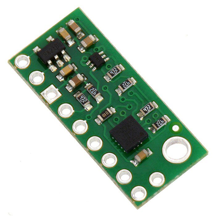
Design of the MEMS electronic gyroscope
The typical design of MEMS gyroscopes includes microelectronic MEMS sensors that incorporate microscale mechanical structures, electronic circuits for measurement and signal processing, and control circuits.
These components are integrated on a single chip , making them small, lightweight and energy-efficient.
The central component is a responsive sensor.
Other sensors are often capacitive sensors, which use changes in electrical capacitance between microscopic elements in response to movements, and piezoelectric sensors, which use the phenomenon of piezoelectricity to generate signals in response to mechanical stresses.
Embedded electronic circuits can amplify, filter and analyze the resulting signals to obtain accurate angular velocity measurements.
The resulting data is processed by control circuits that allow the user to control the gyroscope’s behavior.
This includes all calibration, noise compensation and output processing.
Gyroscope and accelerometer pairing
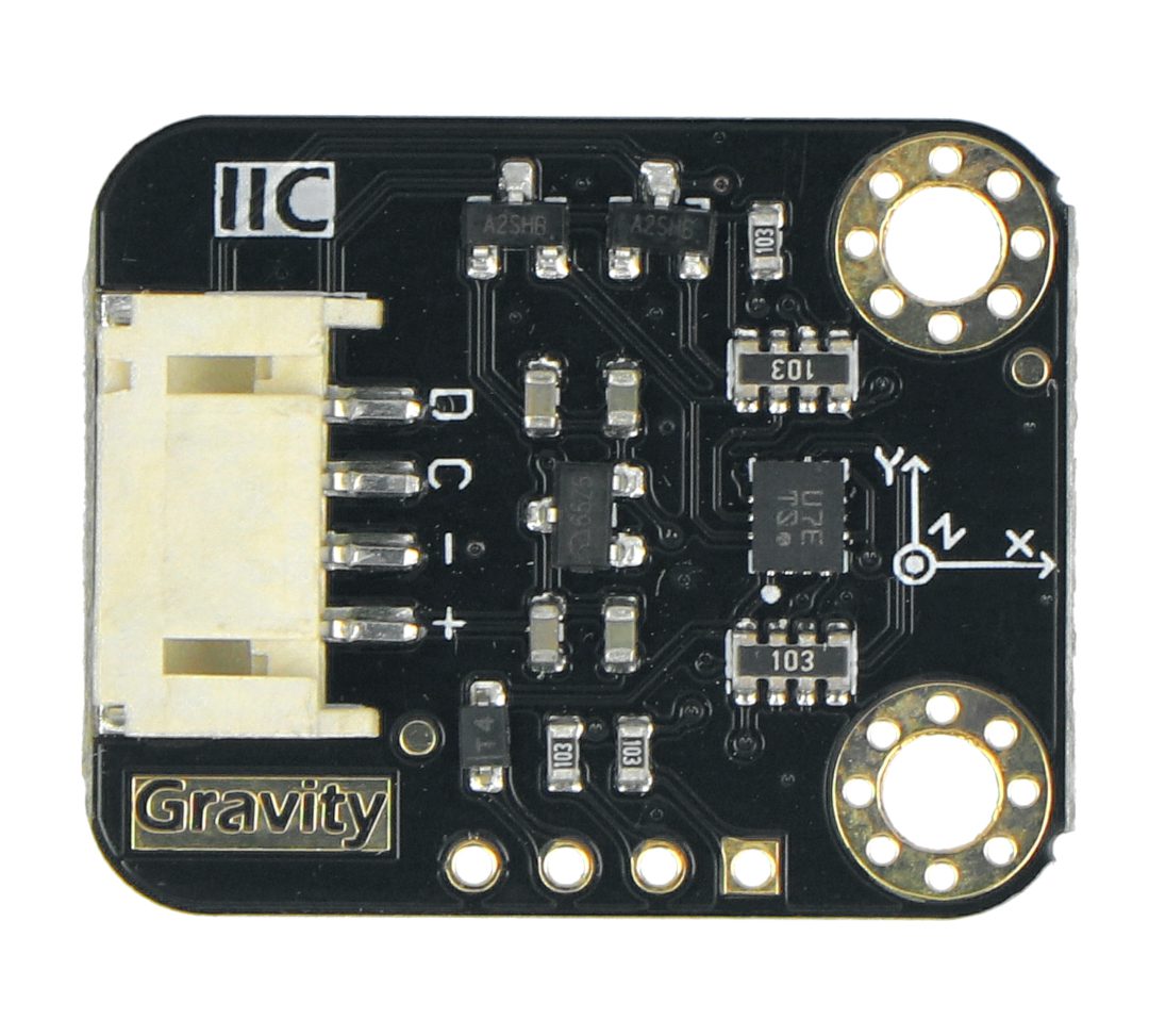
Why is it that in electronic modules and numerous so-called
electronics ecosystems, such as DFRobot Gravity, the gyroscope and accelerometer are so often found in tandem?
The answer lies in 3D space – or, if one prefers, 4D, as this aspect will also appear to some extent in this explanation. Gyroscopes measure the angular velocity of an object’s change in orientation, while accelerometers measure linear acceleration, or changes in an object’s velocity in a linear direction.
When you combine these two types of sensors, you can get complete information about an object’s motion in three-dimensional space.
Gyroscopes can also be susceptible to drift, a certain gradual change in angular velocity measurement values over time, while accelerometers can be susceptible to noise and interference.
By using both sensors simultaneously, these errors can be compensated for and more stable and accurate measurements can be obtained.
In many applications such as image stabilization in cameras, motion controllers in video games or vehicle control systems, gyroscopes and accelerometers are used for stabilization or correction.
Gyroscopes help detect changes in orientation, while accelerometers help detect linear accelerations.
It is also difficult to talk about sensible motion tracking and determining the position of an object without reference to external signals, i.e. inertial navigation systems, where once again combining data from both types of sensors comes to the rescue.
Electronic projects - MEMS gyroscopes
MEMS gyroscopes are readily used in a variety of DIY electronics projects – both simple and advanced.
You can use a MEMS gyroscope in an image stabilization project for video or still cameras.
With a gyroscope, you will be able to detect camera shake or movement so that you can apply the appropriate corrections, resulting in smooth, stable recordings or photos.
Since the gyroscope is well known in aviation, MEMS models can be used in projects to build your own drone or to control the flight of a drone.
They are then used to stabilize position and respond to changes in direction and orientation.
Interesting applications are being drawn in the burgeoning realm of virtual reality (VR) and its derivatives, where something must, after all, be responsible for tracking the movement of the user’s head and enabling an increasingly realistic experience of interaction with the virtual environment.
Choice of electronic gyroscope
Issue one is the gyroscope’ s measurement range, or the maximum angular velocity it can accurately measure. Measurement accuracy is a key factor, especially in applications requiring precise tracking.
Make sure the gyroscope offers enough accuracy for your needs. The gyroscope should also generate measurements as quickly as possible especially in applications such as drone flight control.
For numerous battery-powered devices, it is important that the module offers low power consumption and thus prolongs the device’s operating time on a single charge.
In more elaborate projects and those created from scratch, and especially with microcontrollers, the key issue is the communication interface.
These include UART, SPI, I2C and even analog interfaces.
How useful was this post?
Click on a star to rate it!
Average rating 3.5 / 5. Vote count: 2
No votes so far! Be the first to rate this post.