Table of Contents:
In electronic systems, it is very common that it is necessary to make measurements on the fly so that the actual quantity and the setpoint can be compared with each other.
Most often, this comes down to measuring voltages either directly or indirectly, where the voltage is a secondary quantity whose value corresponds to that of another secondary quantity, such as temperature.
In these as well as similar applications, voltage comparators are used to realize such measurements.
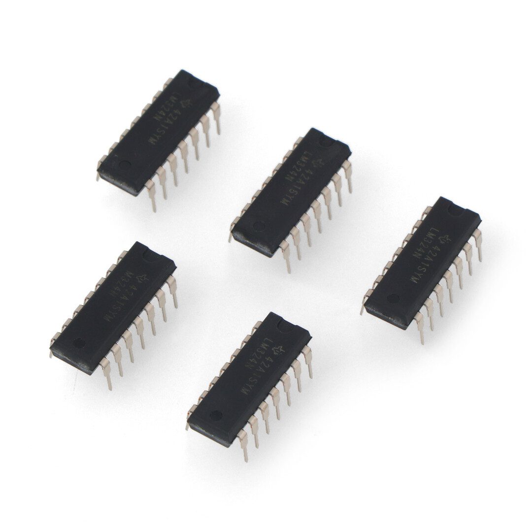
Comparators come in the form of integrated circuits – in this article we will consider the LM324 integrated circuit, which incorporates four independent voltage comparators that share a power supply.
How does the LM324 comparator work?
The LM324 comparator is a popular integrated circuit used in electronics to compare two voltages.
It is a circuit based on bipolar transistors that can be powered by a single voltage source.
The LM324 chip has four independent comparators that can compare voltages between their two inputs.
Two voltages can be applied to each comparator: a reference voltage (usually at the inverting input) and an input voltage (at the other non-inverting input).
The comparator compares these voltages and generates an appropriate response depending on which voltage is higher.
The result of the comparison is a low state (0) or a high state (1) at the output of the comparator, depending on the relationship between the voltages at its inputs.
Comparator vs. operational amplifier
Although the comparator on the schematic is drawn with the same symbol as the integrated operational amplifier (that famous “magic triangle”), the two circuits are different and cannot be used interchangeably.
Comparators have differential inputs and a rail-to-rail output.
Similarly, operational amplifiers.
They are characterized by low offset, high gain, and high co-mode signal attenuation ratio (CMRR).
However, comparators are designed for open-loop operation, control of logic circuits, high-speed operation even in the case of overdrive and acceptance of large differential input voltages.
Operational amplifiers, on the other hand, are designed for closed-loop operation and driving simple resistive or reactive loads – and are not designed to recover quickly from overdrive.
But operational amplifiers are less expensive, are often available as quadruple amplifiers such as.
TL074 and, compared to most comparators, have better offset current and polarization performance.
Using an operational amplifier as a comparator can lead to difficulties for three main reasons: speed, logic controllability and the different side effects of the input structures.
Comparators are designed to work with inputs that have a large voltage difference, while operational amplifiers are designed for closed-loop operation, where the two inputs have very similar potentials.
If an operational amplifier detects a differential input voltage of even a few millivolts, its internal circuitry can saturate.
Recovery of the pre-saturation state can be very slow, and the recovery time can vary widely depending on the level of overdrive and depending on the hardware specifics of the circuit.
Such variability and loss of speed may be undesirable in a comparator.
If the operational amplifier has a rail-to-rail output and is powered by the same power sources as the saturation logic it controls (CMOS or TTL), then the connection is not difficult.
However, if the power supply for the operational amplifier and the logic differs, an additional interface circuit is required to obtain the correct levels, which can be quite complicated.
Finally, the inputs of an operational amplifier usually have high impedance and low polarization current.
However, if a differential input voltage of more than a few hundred millivolts is applied to them, this may no longer be the case, and all sorts of abnormal behavior, such as oscillations, may occur.
Higher overdrive levels can also cause minor damage to the input stages of an operational amplifier, causing a slow build-up of long-term performance changes that may be overlooked during design development.
Battery charging rectifier with LM324 chip
In a battery charging rectifier, the LM324 comparator IC can be used to monitor the voltage on the battery and decide the charging stages.
In such an application, the comparator chip can be used to compare the voltage on the battery with fixed reference voltage values that determine the charging stages, such as charge, hold, full charge.
Based on the result of comparing the battery voltage with the reference voltage, the comparator can control the operation of the charger.
For example, if the voltage on the battery is below a certain level, which indicates the need for charging, the comparator can turn on the charger to charge.
When the voltage on the battery reaches a set value, the comparator can turn off charging.
The comparator can also be used to monitor the voltage on the battery during charging.
If the voltage exceeds the set maximum value, the comparator can stop the charging process to prevent the battery from overcharging, which could lead to battery damage.
The comparator can also be used to control LED indicators or audible signals to inform the user of the battery’s charging status, such as an LED that lights up when the battery is charged, or an audible warning signal when the voltage exceeds a certain acceptable level.
The operation of the comparator in the battery charger is key to ensuring a safe and efficient charging process and prolonging the life of the battery by controlling the charging voltage and current.
How useful was this post?
Click on a star to rate it!
Average rating 5 / 5. Vote count: 1
No votes so far! Be the first to rate this post.