Table of Contents:
Audio technology has many enthusiasts, including among electronics engineers.
Numerous audio amplifiers are created using electron tubes, as well as transistors.
We can meet with combined hybrid designs, in which the power stage is on tubes, and the preamplifier – on transistors, or vice versa.
Designing audio amplifiers, is greatly facilitated by the use of dedicated integrated circuits, such as the LM3886.
This chip is an almost off-the-shelf design solution and is equipped with a number of protections to protect this amplifier from short circuits, overloads and surges.
Audio amplifier on LM3886 - do it yourself!
This article presents the concept of an audio power amplifier based on the LM3886 IC.
The amplifier can deliver 2x 30W-40W power for a 4Ohm load and in bridge mode 80W-100W for an 8Ohm load.
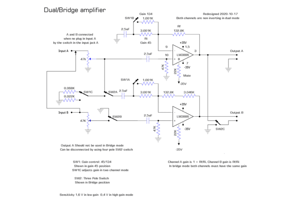
The design of the power amplifier based on the LM3886 IC is based on the datasheet example in application note AN-1192 provided by Texas Instruments.
The upper circuit is a non-inverting amplifier with a gain of 1 + R2/R1.
The lower amplifier inverts the signal with a gain of R2/R1 (where R2 is a resistor in the negative feedback loop).
With a bridge circuit, the problem is to select the resistor values so that both amplifier circuits have the same gain.
To do this, it is best to use metallized resistors made to a 1% tolerance.
The gain of the non-inverting amplifier is 1+ 132.8/3.001 = 45.25, and the gain of the inverting amplifier is (132.8+3046)/1.015 = 45.27.
In order to be able to increase the gain, a gain switch SW1 is included in the design, which reduces the value of the resistance R1 in the short-circuited state to obtain four times the gain.
The non-inverting circuit uses a 1k resistor connected in parallel with 3k, which results in a resistance, 751R.
The inverting gain of the circuit is 1+ 132.8/0.75=177.92 =~ 178.
Switch SW2 allows the amplifier to switch between bridge and stereo mode.
In the “bridge” position, amplifier B is set to inverting, the positive input is grounded, and the output of amplifier A overrides the ground on output B. In stereo mode, both amplifiers operate in non-inverting mode.
Switch SW1C lowers the gain so that amplifiers A and B have equal gain.
The amplifier’s input jacks are connected so that when there is no plug in jack A, the signal is sent to both amplifier A and amplifier B (dual mono signal).
In low-gain mode, 1.6V peak-to-peak input voltage gives maximum output (70Vpp), while in high-gain mode 0.4V is required.
Amplifier power supply
The power supply for the amplifier is a simple design with two large electrolytic capacitors and two film capacitors (with solid dielectric) and a bridge rectifier.
The rectifier is an MB252 (200V/25A).
It is mounted on the same heat sink as the power amplifiers.
Both the rectifier and the LM3886 are galvanically isolated, so no additional insulation is required.
The transformer is a 120VA toroidal transformer with 2x24V symmetrical windings with a rated current capacity of 2.4A per single 24V winding.
Section 4.6 of the AN-1192 documentation gives the output power for various loads, supply voltages and configurations (single, parallel and bridge).
The reason I decided to implement the bridge design was mainly because I had a transformer that could not be used in parallel due to the low voltage.
(A 100 W parallel circuit requires 2×37 V, but the bridge design works with 2×25 V.)
To optimally select a transformer, it is recommended to use the PSU Designer II support application from Duncan Amps.
Amplifier cooling and cooling fan control
During operation, the power amplifier IC gives off a significant amount of heat to the environment.
Therefore, in order to ensure the best possible heat dissipation to the environment and to protect the amplifier from overheating, it is necessary to add active cooling in the form of a heat sink with a fan forcing the circulation of cooling air.
In addition, it is a good idea to equip the cooling system with fan speed control according to the temperature of the heat sink.
Due to the large voltage difference between the input and output, it is not recommended to power the fan from a 12V voltage stabilizer taking power directly from the diode bridge after the transformer, as this can cause high power loss and excessive heating.
Instead, we can use a step-down converter based on a 741 IC (single operational amplifier thermally compensated) as a controller and a PNP BDT30C transistor acting as a switch that charges a 220uF capacitor to 18V, which is a reasonable option for using a 7812 regulator to power the fan.
The circuit uses a 555 timer and a 10k NTC thermistor to control the fill factor of the 555 timer.
It is mounted on the heat sink of the power IC.
A 20k potentiometer is used to adjust the low speed.
The output signal of the 555 is inverted by the NPN transistor BC237 and becomes the control signal (PWM) to the fan.
The fill factor changes from 4.5% to 9% from cold to warm.
The BDT30 transistor and 7812 regulator are mounted on a separate heat sink.
Radiator
The LM3886 power amplifier chip, diode bridge and NTC resistor can be mounted on a copper heat sink plate.
Drill holes and thread for mounting screws using a threading tool.
The PCB with the power amplifier components should be mounted so that the wiring from the power supply and to the speakers is as short as possible.
How useful was this post?
Click on a star to rate it!
Average rating 5 / 5. Vote count: 1
No votes so far! Be the first to rate this post.