Table of Contents:
When designing electronic circuits, it may happen that due to the specific operating conditions of the circuit, it is necessary to provide galvanic separation between one circuit and another.
Such a procedure is performed so that, on the one hand, there is the possibility of communication between them, and on the other hand – so that this is done safely, without fear of damage.
This is especially useful when it is necessary to drive a circuit operating at a much higher voltage than the control circuit.
Optocouplers, also known as optoisolators, are used for this purpose.
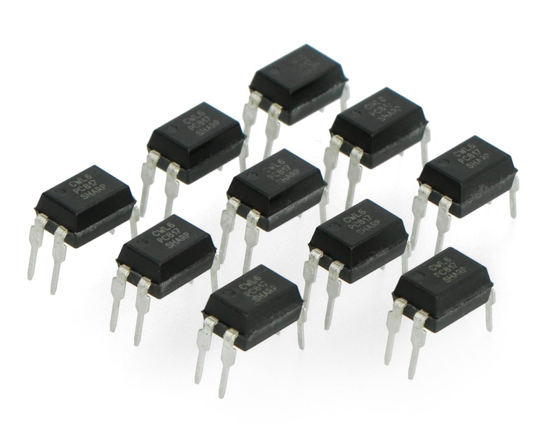
An example of a popular optoisolator, is the PC817 IC, which we will present in this article.
PC817 - general characteristics of the circuit
PC817 is an optoisolator consisting of an infrared diode and a phototransistor.
In electrical circuits, we mainly use filters to remove noise.
A circuit based on a capacitor and resistor always removes noise from the incoming signal, but the value of the capacitor and resistor always depends on the frequency of the incoming signal.
This circuit is only applicable when the incoming signal contains some information or data, but when we simply need to pass a signal from one part of the circuit to another, but the signal contains noise, then we can use a combination of an infrared transmitter and receiver.
In the PC817 optoisolator IC, an IR diode receives a noisy signal from one circuit and passes it to the other part of the circuit via a signal from the frequency contained in the infrared band.
The second part of the circuit receives the signal and then operates according to the design of the downstream part of the target circuit.
The PC817 optocoupler has a small footprint and is available in a variety of housings for both THT and SMD mounting.
The circuit can be directly connected to any low-voltage DC device or microcontroller.
The input voltages will have the same effect on each side of the optocoupler, passing the signal to the receiver, and then the receiver will pass the logic signal as the output signal.
The optocoupler has many applications due to its small and compact size as a control element.
PC817 - pinout description
|
ANODE |
PIN 1 |
Anode of the infrared diode (transmitter side). |
|
CATHODE |
PIN 2 |
Infrared diode cathode. |
|
COLLECTOR |
PIN 3 |
Collector – the output of the photoresistor (receiver side). |
|
EMITTER |
PIN 4 |
Emitter of the photoresistor (receiver side) – this lead is the ground of the power supply on the receiver side. |
PC817 - replacements and other variants
PC817 - practical applications of the optocoupler
The optocoupler has many applications, but due to the development of the IOT industry since 2012, the optocoupler is now increasingly used in everyday life to control various IoT devices, especially in home automation or controlling large electrical loads in industry.
The optocoupler makes it possible to build a zero-crossing detector – thus, you get a change in the AC voltage frequency signal.
Changing the voltage gives you the ability to control the AC current.
The AC load is additionally controlled by triacs.
The main feature of the optocoupler here is the change of the pulse frequency.
The optocoupler is connected to the rectifier by a HIGH resistance in watts, and the rectifier converts the HIGH AC current to HIGH DC current, and the resistance reduces the DC voltage.
The DC voltages coming out of the resistance are lower, but contain noise, which is not usable as a signal.
We use an optocoupler to convert it into a proper signal.
The optocoupler generates the same type of single pulse, no matter how noisy the signal is.
This single pulse is used to detect frequency change events called zero transitions.
This zero crossing allows microcontrollers to control a HIGH AC load with a simple microcontroller.
The PC817 has an internal form of protection in the form of galvanic isolation.
The protection applies to both the input and output.
The optocoupler’s insulation is designed for a breakdown voltage of 5kV.
The optocoupler can be used with an external resistor in high-voltage devices to work with low-voltage devices.
The optocoupler can work with any device with internal interfaces, such as TTL device, microcontrollers, and even at HIGH DC voltage with some internal resistors.
The PC817 optocoupler is equipped with internal reverse current protection.
Due to the unidirectional nature of IR current flow, the PC817 protects the IR from reverse current.
PC817 optocoupler - parameters
- Maximum collector-emitter voltage: 80V
- Maximum collector current: 50mA
- Limit frequency: 80 kHz
- Propagation time: 18us
- Maximum operating temperature: -30*C – +100*C.
- Maximum soldering temperature: 260*C
- Storage temperature: -55*C – 125*C
- Maximum power dissipated: 200mW
- Internal resistance: 100R
PC817 - applications in electronics
The PC817 optocoupler has a very wide range of applications.
Among other things, it can be used in protection such as electrical isolation between the control stage and the power stage in frequency converters.
The PC817 is a very efficient circuit when controlled from microcontrollers.
Simple transistors can be used in addition, but because of the omitted noise factor, the optocoupler can also be used as a switch in high-frequency circuits such as frequency converters and other power electronics.
How useful was this post?
Click on a star to rate it!
Average rating 0 / 5. Vote count: 0
No votes so far! Be the first to rate this post.