Table of Contents:
In this article, we will take a look at the ULN2003 IC based on its technical documentation, including the chip’s leads and their functions.
Control of inductive loads from the level of electronic circuits
If you’ve ever tried to control an electric motor, such as a standard DC brush motor or stepper motor from a microcontroller, such as a PIC, AVR, Raspberry Pi or STM32, you’ve certainly come across the concept of PWM drivers.
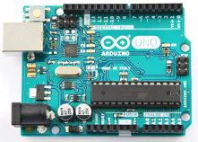
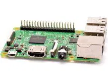
Why do we need PWM controllers? Precisely to control motors, for two main reasons – first, microcontrollers are circuits that usually operate on very low voltages such as 1.8V (BeagleBoard), 3.3V(Raspberry Pi), 5V(Arduino UNO R3), while electric motors controlled from these microcontrollers require power supply with higher voltages, such as 9V, 12V or 24V.
Secondly, electric motors are inductive loads that generate back-polarized electromotive force during winding switching, with values many times exceeding the voltage ratings of the power supply for these motors, which can lead to damage to the microcontroller controlling the motor. For these reasons, we use driver circuits that mediate between the microcontroller and the motor. We can find many solutions of this type in the form of integrated circuits, and one of them is the ULN2003.
If we look at the technical documentation of this IC, we can see that the single output of this chip can handle voltages up to 50V and has a continuous current output of up to 500mA. For these reasons, this chip is great for controlling small electric motors. We can also use this circuit to control larger electric motors, but here it will be necessary to use additional intermediate relays – in this case the microcontroller sends a signal to the ULN2003 driver, which drives signals in the form of voltages applied to the coils of relays whose current circuits (working contacts) are connected to motors – it should be remembered that the coil of the relay is also inductive and generates overvoltages during switching off. Thus, we can use various types of inductive loads such as motors, relays, contactors, electromagnets and other inductive components together with the ULN2003 circuit.
Parameters of the ULN2003 integrated circuit
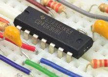
The ULN2003 IC is housed in a 16-pin package, with both SMD and THT versions available. The chip contains seven pairs of transistors working in a Darlington circuit – each of the Darlington pairs is protected by overvoltage diodes, so that the ULN2003 driver can simultaneously support up to seven loads of inductive nature at the same time – each of the Darlington pairs placed inside the ULN2003 IC has a maximum continuous current capacity of up to 500mA, and the peak current that each output can briefly deliver is 600mA, while the maximum output operating voltage for each of the Darlington pairs embedded in the chip is 50V.
Darlington pair
The ULN2003 circuit, has in its structure seven identical dot-to-dot pairs of transistors connected in a Darlington arrangement – a single Darlington pair is composed of two bipolar transistors, which are characterized by an allowable operating voltage of 50V between the collector and emitter of the final transistor in the pair, and a maximum continuous output current of 500mA, and up to 600mA at peak (e.g., when switching a load on the output. The transistors forming a Darlington pair share a common emitter and an open-collector type output.
Surge protection diodes
The ULN2003 IC has built-in surge diodes that protect each of the seven Darlington pairs from damage due to the back-polarized electromotive forcecreated by switching off circuits containing inductances. This means that when we have relays or motors connected to the output of the circuit, we don’t need to connect additional surge diodes, since they are built into the ULN2003 circuit structure as standard.
Practical applications of the ULN2003 integrated circuit
The ULN2003 driver chip has a wide range of practical applications in both amateur and professional electronics. The most important applications of this chip include buffers in logic circuits, drivers for communication lines, control of relays and contactors, control of indicator lamps, control of segmented LED displays, as well as control of electric motors, especially DC brush motors and stepper motors.
ULN2003 - control of LED display segments
One of the common applications of the ULN2003 chip, is the control of LEDs, including LEDs that are seven-segment displays. The control can be implemented by connecting microcontroller pins configured as outputs to the control inputs of the ULN2003 chip, while we connect the anodes of the LEDs constituting the display segments (for an LED display with a common cathode) to the outputs of the ULN2003 chip. When we give a high logic state to the corresponding inputs of the circuit, then a high logic state will appear on the corresponding outputs – e.g., a high state on the IN1 input will cause a high state on the OUT1 output and light up the LED segment whose anode is connected to this output, respectively, and pulling down the logic state on the IN1 input to a low level, respectively, will cause a low level on the OUT1 output and turn off the target controlled LED display segment. Note that in order to display the corresponding character (e.g., the number “3”), we must program the microcontroller to drive the corresponding inputs of the ULN2003 chip and the segments connected to its outputs.
How useful was this post?
Click on a star to rate it!
Average rating 0 / 5. Vote count: 0
No votes so far! Be the first to rate this post.


