Table of Contents:
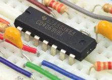
Often when we want to drive high-current loads from a microcontroller or TTL/CMOS ICs, we need to use external circuits to amplify the control signals. In this article, we present one of the ICs that provide a remedy for this problem. Meet the ULN2803!
Key features of the ULN2803 chip
The ULN2803 is an integrated circuit that incorporates a ladder of Darlington transistors, allowing high output voltages and currents. The pairs of Darlington transistors are connected in parallel inside the ULN2803 chip structure, thus increasing the output current capacity of the chip. Inside the ULN2803 circuit structure are eight pairs of Darlington-type NPN transistors with high voltage outputs and surge diodes connected in a common cathode arrangement – these diodes, protect the circuit’s outputs from overvoltages caused by disconnecting circuits with inductances. The current capacity of a single Darlington pair in the ULN2803 circuit is about 500mA at continuous current consumption, which means that the total current capacity of the circuit with eight switched outputs is about 4A.
Technical specifications of the ULN2803 integrated circuit
The technical specification of the ULN2803 circuit specifies the following features: The maximum allowable collector-emitter voltage of each pair of Darlington transistors is 50V, and the maximum current load of a single output of each pair of Darlington transistors is 500mA. The maximum base-emitter voltage of each single Darlington pair is 30V. Each of the eight Darlington pairs embedded inside the ULN2803 IC has a built-in surge protection diode, which can conduct a maximum current of 500mA. The propagation time of the ULN2803 chip is 130ns for the rising edge and 20us for the falling edge. The operating temperature range of the ULN2803 chip is -65*C to +150*C. In order for this IC to function, it is not required to connect an additional auxiliary voltage source, as is the case, for example, in microcontrollers, operational amplifiers and many other ICs.
Advantages of the ULN2803 chip
The ULN2803 IC enables switching of relatively high currents and high voltages, values that are unacceptable in microcontrollers needed to provide control signals for loads with increased current consumption. The ULN2803 IC, which contains eight pairs of NPN transistors in Darlington topology and eight protection diodes, makes it possible to control the real-time power supply of such loads as incandescent lights, relays, contactors, motors, solenoids and also other loads in which their inductance is a key parameter.
Replacements for the ULN2803 integrated circuit
There is no currently available replacement for the ULN2803 chip that is pinout-compatible with it, but you can find replacements with similar functionality that admittedly differ in pinout from the case, such as ULN2003 and ULN2004. We can also build in an equivalent of this IC based on discrete MOSFETs or eight discrete Darlington NPN transistors, which will behave exactly the same as those blended into the structure of the ULN2803 IC – but here you should also remember to connect surge diodes.
Applications of the ULN2803 integrated circuit
The ULN2803 IC can be used in a number of ways – for example, we can use it to control loads containing inductance. The ladder of Darlington NPN transistors placed in the ULN2803 chip, in fact, acts as eight independent switches that can be turned on and off according to our design – each single pair of Darlington NPN transistors can handle loads with increased current consumption based on the low-voltage logic signals applied to the inputs of the ULN2803 chip. If we want to control multiple loads simultaneously from the ULN2803 chip, it can control them independently – up to eight loads simultaneously.
Moreover, MOSFET transistors or Darlington NPN transistors in discrete form can be successfully replaced by this circuit. We can also use it for control in programmable load sharing circuits – if, for example, we have loads of varying current consumption connected to the output of the circuit, we can then connect the circuit in the manner of a switched switch matrix so that high-power loads can be handled.
Bipolar NPN transistors in Darlington circuit - principle of operation
The ULN2803 IC in its structure contains eight pairs of NPN bipolar transistors connected in a Darlington pattern, which provide the correspondingly large current amplification necessary to supply the loads connected at the output. Typically, single transistors are used for current amplification, but the Darlington transistors allow even greater current amplification, thanks to a special cascade connection. Darlington transistors are two NPN bipolar transistors that operate on the principle of two-stage current amplification. When the control current to the base of the first transistor, a proportionally increased current is obtained at its output. This amplified current is then applied to the base of the second transistor, whose collector-emitter circuit allows even greater current amplification.
When, on the other hand, there is no current applied to the base of the Darlington transistor, its output then behaves like an opened switch causing no current to flow in the target circuit. What’s more, because of the solid-state technology, the turn-on and turn-off times are incomparably shorter than those of electromagnetic relays, which is crucial when you want to maintain the highest possible control precision.
How useful was this post?
Click on a star to rate it!
Average rating 0 / 5. Vote count: 0
No votes so far! Be the first to rate this post.


