Table of Contents:
Adjustable DC voltage converters are very versatile and easy-to-use modules that allow you to power electronic devices that require a non-standard supply voltage. In this article, we will take a look at the XL4015 step-down converter module, which allows lowering the supply voltage allowing the output to achieve a DC voltage in the range of 1.3V to 36V and a maximum current capacity of 5A.
XL4015 - technical specifications of the module
XL4015 step-down converter module, is characterized by the following technical parameters: The input voltage range supported by this module includes a voltage from 8V to 36V, and the output voltage of this module can be adjusted from 1.3V to 36V – it should be taken into account here that the input voltage must be higher than the required output voltage for the inverter to turn on. The maximum current capacity of this module is 5A. The voltage regulation accuracy range is 2.5%, and the current load regulation range has an accuracy of up to 0.5%. The maximum noise level of the inverter’s output is 50mV in the 20MHz frequency band. The keying frequency of the inverter is 300kHz, and the efficiency of the inverter under the best conditions is 95%. The module has no galvanic isolation between input and output and can operate in voltage source or current source mode. The operating temperature range of the module is -40*C to +85*C.
Construction of XL4015 module - voltage and current regulation and LED optical signaling
On the PCB of the XL4015 module, in addition to the blue ARK-type screw connectors, two multi-turn mounting potentiometers draw attention. It is with these potentiometers that we can set the voltage at the output of the inverter and adjust the maximum current load of its output. On the PCB we can also find three LEDs, which inform us about the operating mode of the inverter. The first LED, located closest to the inverter’s input connector, informs us that the inverter is operating in current source mode, while the other two LEDs have been placed here mainly for use in battery charging applications. The first one indicates that the battery is charging, and the second one informs the user that the battery is fully charged. What’s more, using this inverter as a general-purpose power supply, the battery charging LED indicator here will then perform the function of informing the user that a current-consuming load is connected to the inverter’s output.
By slowly turning the screw of the multi-turn potentiometer located at the IC, clockwise, we gradually increase the output voltage of the inverter, while turning the adjustment screw in the opposite direction, we decrease this voltage. Similarly, by turning the screw of the second mounting potentiometer clockwise, we increase the value of the maximum output current limit, while turning in the opposite direction, we decrease this value. Before connecting a load to the output of the inverter, it is recommended that the output voltage be set first, followed by the maximum value of the output current.
Construction of the XL4015 module - semiconductors
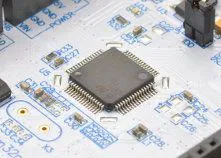
On the PCB of the XL4015 module, there are several semiconductor components that are necessary to implement the process of reducing and stabilizing the voltage at the output of this converter. At the heart of the module is the XL4015 IC, which is a step-down DC/DC converter that uses PWM control with a frequency of 180kHz. This IC features very high efficiency, low self-noise and very high stability of parameters at the output. Moreover, the internal PWM controller allows linear adjustment of the control signal’s fill factor from 0 to 100%. The XL4015 IC also has built-in overcurrent protection, which protects the circuit from short circuits and, in the event of a short circuit, automatically reduces the PWM modulation frequency to 48kHz.
Other semiconductors located on the PCB of the module shown here include a 78L05 linear stabilizer that provides a precisely regulated 5V DC voltage at the output, a TL431 shunt regulator based on a Zener diode that provides a precise reference voltage source, and an LM358 operational amplifier that is hidden next to a 47uH choke wound on a toroidal core. There is also a high-speed SK54 Schottky diode and two 220uF/50V electrolytic capacitors. Meanwhile, on the bottom of the PCB, a 50mR measurement resistor has been placed, which is responsible for detecting the flow of load current.
DC/DC converter XL4015 - adjusting output parameters in an example application
Before we run the inverter in our application, we need to make the necessary assumptions according to the power requirements of our load – whether we want to power a simple light bulb or an elaborate audio amplifier. Let’s assume that we want a current of 1A at the output voltage of 9VDC. First, turn on the module and connect a multimeter set as a DC voltage voltmeter to the output – set the multi-turn voltage adjustment potentiometer to get a reading of 9.0VDC. Then switch the multimeter to DC current measurement and turn the second mounting potentiometer to get a reading of 1.0A. Now we connect the load to the output of the inverter. It is worth noting that tuning one potentiometer may slightly affect the setting of the other, but this is fortunately not a serious problem. For a quick test, we can use the module to power a single LED with a white light color and a power consumption of 10W, through a 12VDC laboratory power supply with a minimum current capacity of 2A. We adjust the output voltage and current according to the power requirements of the target receiver.
How useful was this post?
Click on a star to rate it!
Average rating 3.8 / 5. Vote count: 6
No votes so far! Be the first to rate this post.


