Table of Contents:
- 1 What is Arduino?
- 2 Where did the name Arduino come from?
- 3 Which Arduino board should you buy to get started?
- 4 Which microcontroller chip is used in Arduino boards?
- 5 Analog vs digital pinouts
- 6 How is the Arduino programming language different from the C programming language?
- 7 What are the basic commands used in an Arduino programming language?
- 8 How to control the high power devices via Arduino?
- 9 What’s next?
Arduino is undoubtedly the most popular embedded platform used by hobbyists, students and electronics designers. It provides a lot of possibilities as it’s evidenced by tens of thousands of projects posted on the Internet by the international community of users. In this article, we present you a short guide in the form of questions and answers, thanks to which you will learn the most important information about the Arduino ecosystem.
What is Arduino?
Arduino is an ecosystem consisting of a PCB platform with a microcontroller chip and input / outputs, Arduino IDE software and additional hardware extensions such as Arduino Shield. The Arduino project assumed the creation of a device with which everyone would be able to learn the basics of programming and electronics, even if you had not had practical contact with these issues before. A further goal is to expand skills, thanks to which the user will be able to design more and more complex applications, e.g. robots, Wi-Fi communication and smart home devices.

Where did the name Arduino come from?
Here’s a quick history lesson. Most often there is a legend behind the names of various companies or products. It was a bit similar to those famous blue boards with Atmega MCUs. The name Arduino is a reference to Arduino cafe in italian Ivrea – this was the place where the creators of the Arduino project met after hours. The second source of the Arduino boards came from the Arduin of Ivrea – the king of Italy living at the turn of the X and XI centuries A.D.
Which Arduino board should you buy to get started?
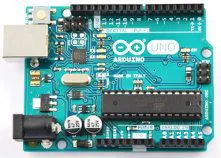
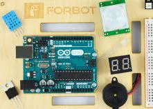
To get started with Arduino successfully, especially if you are new to coding and electronics, you have to choose the proper development board at first. Generally, there are over a dozen different types of Arduino boards available for sale, which differ in size, structure and the possibility of cooperation with peripheral devices. However, the most popular choice is the Arduino UNO R3 board – an excellent choice to start with, and by the way it’s the one featured at the pic above. The huge popularity of the Arduino UNO Rev3 has led to the licensing of other companies that produce licensed clones of Arduino boards that are completely compatible with the software and hardware for original Arduino.
Which microcontroller chip is used in Arduino boards?
Most Arduino boards use the Atmega328P chip, which has an 8-bit AVR microcontroller designed according to the Harvard/RISC architecture. The clock frequency of the Atmega328P microcontroller is 16MHz (external crystal oscillator on an Arduino R3 UNO board). Unlike frequencies clocked at GHz range used in a full-sized PCs and mobile phones, the Atmega238P has built-in memory chips in its structure, and their instruction set is reduced to the minimum necessary, so they are used in a variety of embedded systems applications designed to perform a strictly limited range of tasks. The capacity of individual memories of the Atmega328P microcontroller is: FLASH – 32kB, RAM – 2kB and EEPROM – 1kB. In the case of the Arduino UNO R3 board, the Atmega328P microcontroller is in the DIL28 package.
Analog vs digital pinouts
The Arduino board has sections that allow you to connect external devices thanks to onboard microcontroller pinouts. The “DIGITAL” section consists of 14 digital TTL-compatible pins, which can be programmatically set to “input”, “input pullup” or as an “output”. Among the digital pins, we have here six PWM channels, which provide the pulse-width modulated waveform at 490Hz as default frequency and 1% -99% duty cycle. Let’s take a look on the second border of the board. There’s an “ANALOG IN” section, which consists of six analog inputs which are connected to ports PC0 – PC5 of the built-in microcontroller, which are the analog-to-digital converter inputs. The ADC resolution is 10 bits. This means that for the TTL level (5V), the voltage reading at the converter input is performed with an accuracy of 4.90mV.
How is the Arduino programming language different from the C programming language?
The programming language for Arduino is actually a C/C++ language with simplified syntax. It contains additional libraries. Below is an example program code in the Arduino environment with explanations:
					void setup() //Initial settings (done only one time after each powerup)
{
    pinMode(2,OUTPUT); //Setting pin 2 as an output
}

void loop() //actual program instructions (repeated in a loop)
{
    digitalWrite(2,HIGH); //Pin 2 goes logic “HIGH” - LED turned on
    delay(500); //Waiting for a half second

    digitalWrite(2,LOW); //Pin 2 goes logic “LOW” - LED turned off
    delay(500); //Waiting for a half second

}
And here is a regular C code written for a regular AVR microcontroller (without the Arduino bootloader), which provides exactly the same hardware functionality:
					#define F_CPU 16000000UL //Setting up the MCU clock frequency for a 16MHz
#include <avr/io.h> //Initializing the inputs/outputs library
#include <util/delay.h> //Initializing the delay library

int main() //Actual program instructions (repeated in a loop)
{

    DDRD |= 1 << PIND2; //Setting up the pin 2 of the D register as an output

    while (1) //”while” loop is described by the following conditions
    {

        PORTD |= 1 << PIND2; //Pin PD2 goes logic “HIGH” - LED turned on
        _delay_ms(500); //Waiting for a half second

        PORTD &= ~(1 << PIND2); //Pin PD2 goes logic “LOW” - LED turned off
        _delay_ms(500); //Waiting for a half second

    }

}
Thanks to this comparison you can see that the code written in a regular C is much more detailed, although it performs the same function for the same pinout of the microcontroller (yes, the pinout no. 2 in the “DIGITAL” section of the Arduino UNO R3 board is an actual PD2 pinout of the Atmega328P). Looking at these two short codes shows that the program code in the Arduino IDE is greatly simplified and does not even require knowing the datasheet of the microcontroller chip. Hence, after the successful software installation, Arduino board is acting like a sort of plug-and-play device.
What are the basic commands used in an Arduino programming language?
If you want to write some fresh code for your new project, regardless of its complexity, it’s definitely worth knowing some of the most basic commands that are used in an Arduino IDE workspace. Here are most important ones with an explanation:
digitalRead(3); – reading the logic state on the digital pin 3;
digitalWrite(4, HIGH); – assigning a high logic state to the digital pin 4;
pinMode(5, INPUT); – setting pin 5 to input mode;
analogRead(A0); – reading the voltage value on the analog pin 0 (“A0”);
analogWrite(A1, 512); – setting the value 512 on the analog pin 1 (“A1”) – the ADC converter in the Arduino Uno has a 10-bit resolution, so it can read 1024 voltage values at the input. If the program reads the value “512”, it means that for a supply voltage of 5,0V, the measured voltage value at the “A1” input is 2,5V;
serial.begin(9600); – setting the data transmission rate (baud rate) to 9600b/s.
How to control the high power devices via Arduino?
Single arduino pin can provide a current up to 40mA. You can power up single LEDs, sensors and other low-power components directly from it. Arduino can also be used to control electric motors and other devices that consume hundreds of watts of power. But how to do it? Is there any risk of causing damage to our Arduino by connecting such devices? Yes there is. Powering the motor or lighting directly from Arduino pinouts would lead to permanent damage very quickly. Fortunately, transistors and relays – elements that can switch high-power electrical circuits by appropriate actuation – had been invented many years ago. Thanks to this, you can control the load from Arduino through the NPN BJT (Bipolar Junction Transistor) connected to a digital pin (set as “OUTPUT”). The base of the transistor you have to connect via current limiting resistor, but if instead of the NPN BJT, you want to use N-channel FET (Field Effect Transistor) – you’ll need two resistors – first one between Arduino digital pin and gate of the transistor and second one – between gate and ground. If you use an electromechanical relay with Arduino – make sure, the coil voltage is 5V. For the higher coil voltages, use the transistor as the switch that controls the relay – and regardless of the coil voltage – please DO NOT forget about the flyback protection diode hooked up in parallel with the coil and cathode to the VCC!
What’s next?
There are several ways to approach Arduino. You can use it as a hobby accessory in your workbench, but if you plan to work professionally as an electronics developer, consider Arduino as a preliminary step before you start your adventure with low-level programming made of flesh and bone. If you find that you have mastered Arduino at a satisfactory level, you may definitely be interested in programming STM32 microcontrollers. You can get both Arduino and STM32 kits from the Botland Store. I hope that you find this Q&A helpful even if you already have a lot of experience with Arduino but want to know some tidbits about it.
How useful was this post?
Click on a star to rate it!
Average rating 0 / 5. Vote count: 0
No votes so far! Be the first to rate this post.


