Table of Contents:
Another ESP32 series tutorial. This time we will connect a PIR motion sensor and an OLED display. The motion sensor can be successfully used as a component to for example turn on the light or turn on the alarm when motion is detected. We will also use the OLED display, which we have also used in previous articles, on which we will display information when motion is detected. In this article we will also use an LED that will be switched on when movement is detected by the SR501 PIR sensor.
What will you need to create the project?
To complete the project we will need an ESP32 module, an SR501 PIR sensor, an LED and an OLED display. All necessary accessories can also be found in the kit we prepared with the ESP32 module.
The full list of components used can be found below:
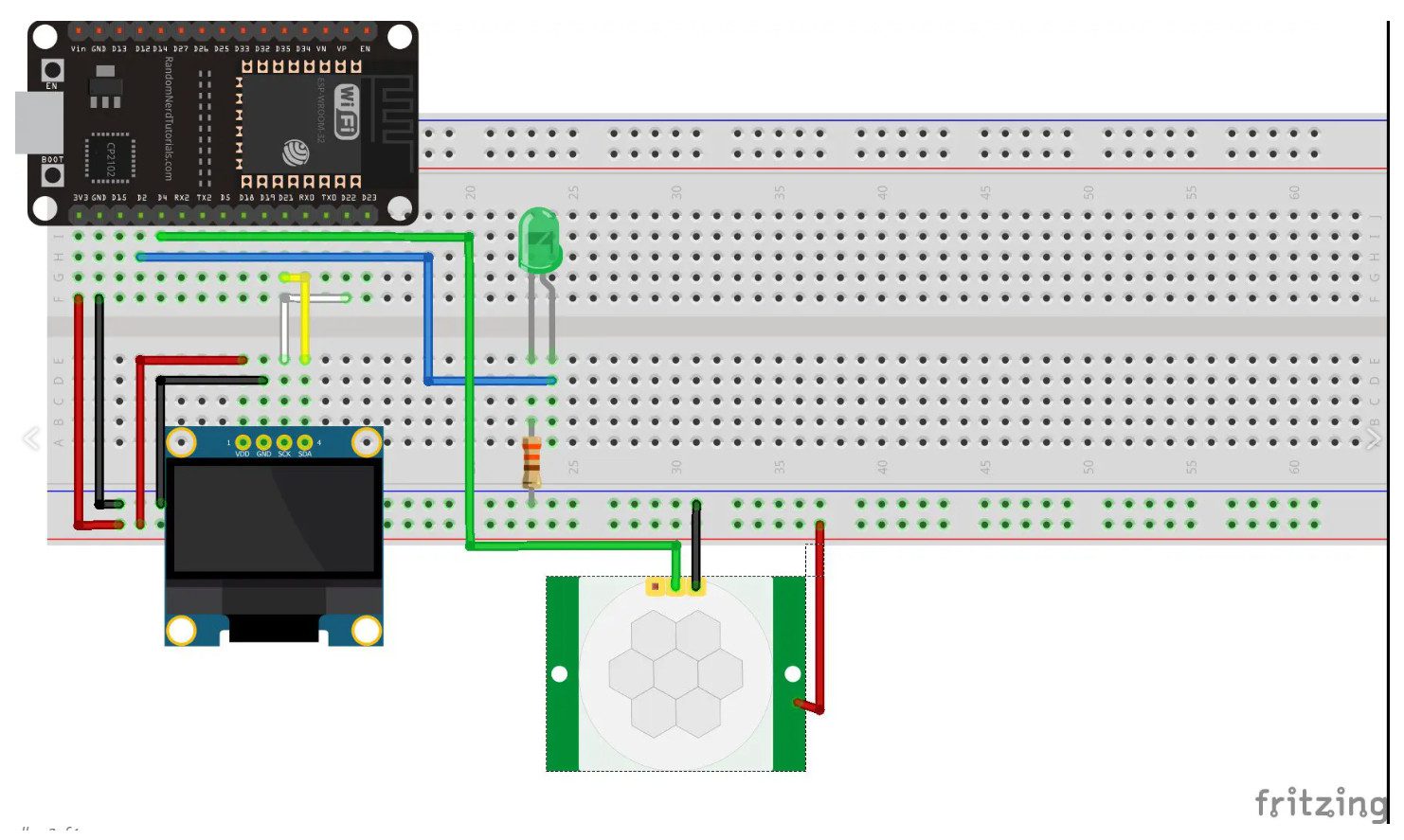
ESP32 - connecting components
Due to its design, the SR501 PIR motion sensor cannot be just plugged into a contact board, so we connected it to the ESP32 using female-to-male wires. PIR communicates through a digital pin. It is powered by 5 V, but it can also be done by pin on the jumper to which the 3.3 V voltage regulator has been pulled up. The sensor is connected to pin 4. The LED should be connected using a 330 Ω resistor to pin 2, and the display respectively to I2C pins 21 and 22.
Required Arduino libraries
In this project only libraries are required for the OLED display to work properly with the SH1106 controller:
The libraries downloaded as a .zip package are installed in the Arduino IDE environment in Sketch menu.
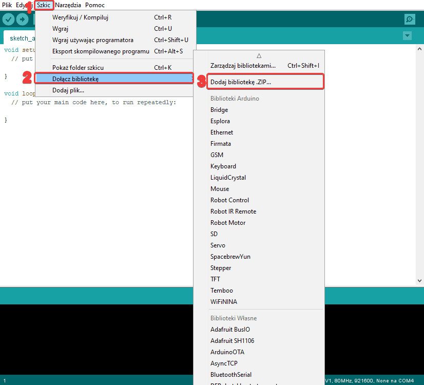
A window will appear where you search for the location of the downloaded packages, then select the .zip library and select the Open button.
Program for ESP32 module
After connecting the modules to the ESP32 and uploading the libraries for the OLED display, you can start programming the chip. Following code will make the LED light up when motion is detected and the appropriate message will appear on the OLED screen.
#include <SPI.h>
#include <Wire.h>
#include <Adafruit_GFX.h>
#include <Adafruit_SH1106.h>
//definiujemy piny I2C, do których podłączony został wyświetlacz
#define OLED_SDA 21
#define OLED_SCL 22
int inputPin = 4; //definiujemy pin, do którego podłączony został czujnik ruchu
Adafruit_SH1106 display(21, 22); //definiujemy piny, do których podłączony został wyświetlacz
void setup() {
pinMode(inputPin, INPUT); //deklarujemy pin 4 jako INPUT
pinMode(2, OUTPUT); //definiujemy pin, do którego podłączona została dioda LED i ustawiamy go na OUTPUT
display.begin(SH1106_SWITCHCAPVCC, 0x3C); //definiujemy rodzaj użytego wyświetlacza oraz adres I2C
}
void loop() {
int val = digitalRead(inputPin);
//gdy na pinie 4 pojawi się stan wysoki, pin 2 przejdzie w stan wysoki i na ekranie pojawi się stosowny komunikat
if (val == HIGH) {
display.setTextColor(WHITE);
display.setCursor(0, 0);
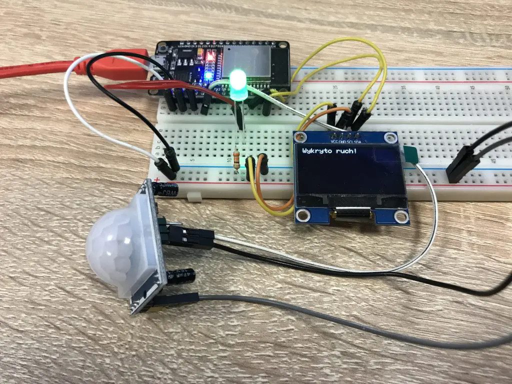
display.println("Wykryto ruch!");
display.display();
display.clearDisplay();
digitalWrite(2, HIGH);
}
//gdy na pinie 4 pojawi się stan niski, pin 2 przejdzie w stan niski i na ekranie pojawi się stosowny komunikat
else {
display.setTextColor(WHITE);
display.setCursor(0, 0);
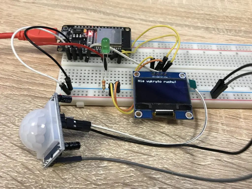
display.println("Nie wykryto ruchu!");
display.display();
display.clearDisplay();
digitalWrite(2, LOW);
}
delay(1000);
}
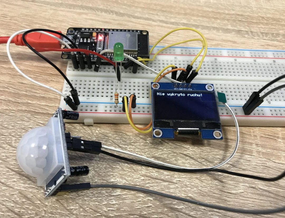
The final result:
We also invite you to read other articles on our blog!
How useful was this post?
Click on a star to rate it!
Average rating 5 / 5. Vote count: 1
No votes so far! Be the first to rate this post.