Table of Contents:
TV manufacturers often add various options that are supposed to make their devices easier and more accessible to the user. However, they usually introduce just aesthetic functions – one of such features is the ambient lighting system that creates a lighting effect on the wall behind the TV. Its colors change according to the picture displayed.
You can just buy a TV with built-in ambient lights… but you can also create such a system yourself!
What do we need to realize this project?
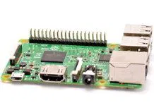
To build an ambient lighting system you need several components. Of course you need the Raspberry Pi minicomputer with a power supply and a memory card. To capture the picture from the device that sends it to your TV, you need an HDMI splitter – a device that splits the signal into two feeds. Then, we need to convert the picture into an analog image signal using an HDMI -> AV converter. Your Raspberry will receive this signal through its AV -> USB converter. To create the ambient lighting system, we also need a light source – we recommend using APA102 addressable LED strips. The list of products you need is below:
- Raspberry Pi Zero W,
- Memory card for your minicomputer,
- 5V power supply unit, microUSB,
- AC -> USB Converter,
- HDMI -> AV Converter,
- HDMI Splitter,
- Additional HDMI cables (2),
- Addressable LED strip APA102,
- OTG microUSB -> USB cable,
- 5V power supply unit,
- 12V power supply unit + a power cord,
- Male-male RCA connector (3),
- Hub for powering converters and splitters.
Click on the button below to check the complete shopping list:
In addition to the electronic components, you will also need a soldering iron, some wires to connect pieces of tape, a cable with a female gold pin, wire cutters and of course the willingness to create your own lighting system!
Initial configuration of your Raspberry Pi
To In order to set up the lighting, we have to prepare our Raspberry. First, we install the system and add files that will allow you to connect the device to a Wi-Fi network and use SSH. Then, we connect to the RPi using Putty, and update the Raspberry (the whole procedure should be done as described in the Smart Home System Guide). Here we are now:

When the Raspberry software is installed and updated successfully, we can unplug the device from the power supply and deal with the more tangible part of this project.
Installation of LEDs on the TV
To make the effect visible, we have to fix the LEDs on the TV Of course we first have to cut the strip into lengths that correspond to the edge lengths of our TV. Remember that there must be the same number of LEDs on the top and bottom side and the same number of LEDs on the left and right side. When the strips are prepared, we can solder them to the wires. It is good to concentrate on the correct laying of the strips at this stage. There are arrows printed on the strip, and you should be careful to arrange them in a clockwise direction, as shown in the figure below.

Where there is a “1” in the above diagram, the first LED and the wires for controlling and powering the entire strip should be present. We can solder the ground of our 12V power supply to the black wire and the VCC to the red wire. You will notice that we have two wires left – here we need to use the prefabricated wires with female gold pins, cut them off at one of the sockets and solder them to the free wires of the strip. The green wire is the “Clock Pin” and the yellow wire is the “Data Pin”.
How to capture the picture so that no one notices?
It is a very simple procedure. Let’s start by connecting the HDMI cable plugged to the picture source to the splitter input. In my case, the image source is the console with the video services installed. If you are using a set-top box or a Blu-Ray / DVD player, use the cable that delivers the signal from that device. Connect the HDMI cables to both outputs of the splitter. One should be connected to the previously used HDMI connector on TV, the other to the converter. The converter has three outputs: CVBS, usually marked yellow, Audio (L) – white, and Audio (R) – red. Use the connectors to hook the converter to the video grabber. Then connect the grabber to your Raspberry with an OTG cable. The HDMI -> AC splitter and converter need a power supply: both devices come with USB cables, so we plug them to the hub. If we have an active high-speed USB hub, we can connect our Raspberry to it. If we have a passive hub, we only connect the splitter and the HDMI -> AV converter. The splitter and converter use very little power, so you can simply try connecting the passive hub directly to the USB port on your TV. Does this seem complicated to you? Just look at the scheme below and everything will become easy.

Once you have hooked everything according to the scheme, you can connect the female gold pins coming out of the strip. Connect the “Data Pin” to pin 19 (not to be confused with GPIO19), then connect the “Clock Pin” to pin 23. If you are not sure where they are, here is a little hint:

Ready? Now let’s get everything hooked up to the power and finish the configuration.
Software configuration
When all connections are complete, we can move on to the next step. We need to download the HyperCon software, preferably from the project’s official website. We need Java to run it, which can be downloaded here. After downloading it, double-click on the file and you will see the image below.

Now click on the “SSH” tab. Enter the address of your Raspberry in the “Target IP” field and then click “Connect”. Once connected, click “Show Traffic”; if you get an image like the one below, it means that HyperCon has successfully connected to your Raspberry.

Now we want to install Hyperion on the Raspberry. To do this, click on the “Inst./Upd. Hyperion”. When a selection window appears, click “Yes” and wait a few moments. Once the installation is complete, the terminal window will appear:
After we have installed Hyperion on the Raspberry, we can continue with the creation of the configuration file. First, click on the “Hardware” tab. In the “Device” field we have to select the LED strip. In our case it is APA102. At the bottom, in “RGB Byte Order”, we change “RGB” to “BGR”. In the “Construction” field, we complete the information about our LEDs. In “LEDs horizontal” we enter the number of LEDs we have on the top edge of the TV (of course the same number of LEDs is also at the bottom edge) – in my case it’s 47 LEDs. In “LEDs Left” and “LEDs Right” we enter the number of LEDs we have on the right and left edge – in my case it’s 21 LEDs. In “1st LED offset” we have to enter a value that adjusts the position of our LEDs so that the setting is correct. The lower left corner of the screen simulation should read “0”. In “Blackborder Detection”, check the “Enabled” checkbox, and in “Threshold [%]”, enter the value “5”. The configuration of the “Hardware” tab should look like this:

Now we go to the “Process” tab; here we only need to change only one parameter, “Update Freq. [Hz]”. This parameter determines the picture sampling. The console sends the image at 30fps, so we have to set it to “30”. However, if you are using a player with a frequency of 60fps, you can use the higher value.

Once you change the frequency, go to the “Grabber” tab and uncheck the “Enabled” checkbox in the “Internal Frame Grabber” section, and then check the checkbox in the “GrabberV4L2” section.
Now we return to the “SSH” tab. Click the “Create Hyperion Configuration” button at the bottom of the tab and select the location. After saving the configuration file in the “SSH – Send Hyperion Configuration” field, click “Local Config Path”, select the location of the previously saved file and click “Send Config”. The last operation we need to perform is to click “Start”. Now a glowing light should appear behind our TV set, as shown in the picture below.
Done! Now you can enjoy a truly unique atmosphere in your room.
How useful was this post?
Click on a star to rate it!
Average rating 0 / 5. Vote count: 0
No votes so far! Be the first to rate this post.


