Table of Contents:
TL431 are three-terminal adjustable voltage regulator ICs. They have a certain thermal stability in automotive and commercial temperature ranges. Similar control ICs can be found in mobile device chargers, consumer power supplies, automotive electronics or LED lighting. The TL431 output voltage can be set to any value between approx. 2.5V a 36V using two external resistors at up to 100mA.
These devices have a typical output impedance of 0.2Ω. The active output circuit provides very sharp turn-on characteristics, making these devices excellent replacements for Zener diodes in switching power supplies, for example. The TL432 has exactly the same functionality and electrical specifications as the TL431 device, but has different pinouts for DBV, DBZ and PK packages. It works well in converters, voltage stabilizers, as a compensation element in temperature-related applications and wherever regulated voltage and current reference and voltage monitoring are required.
Features and applications of TL431
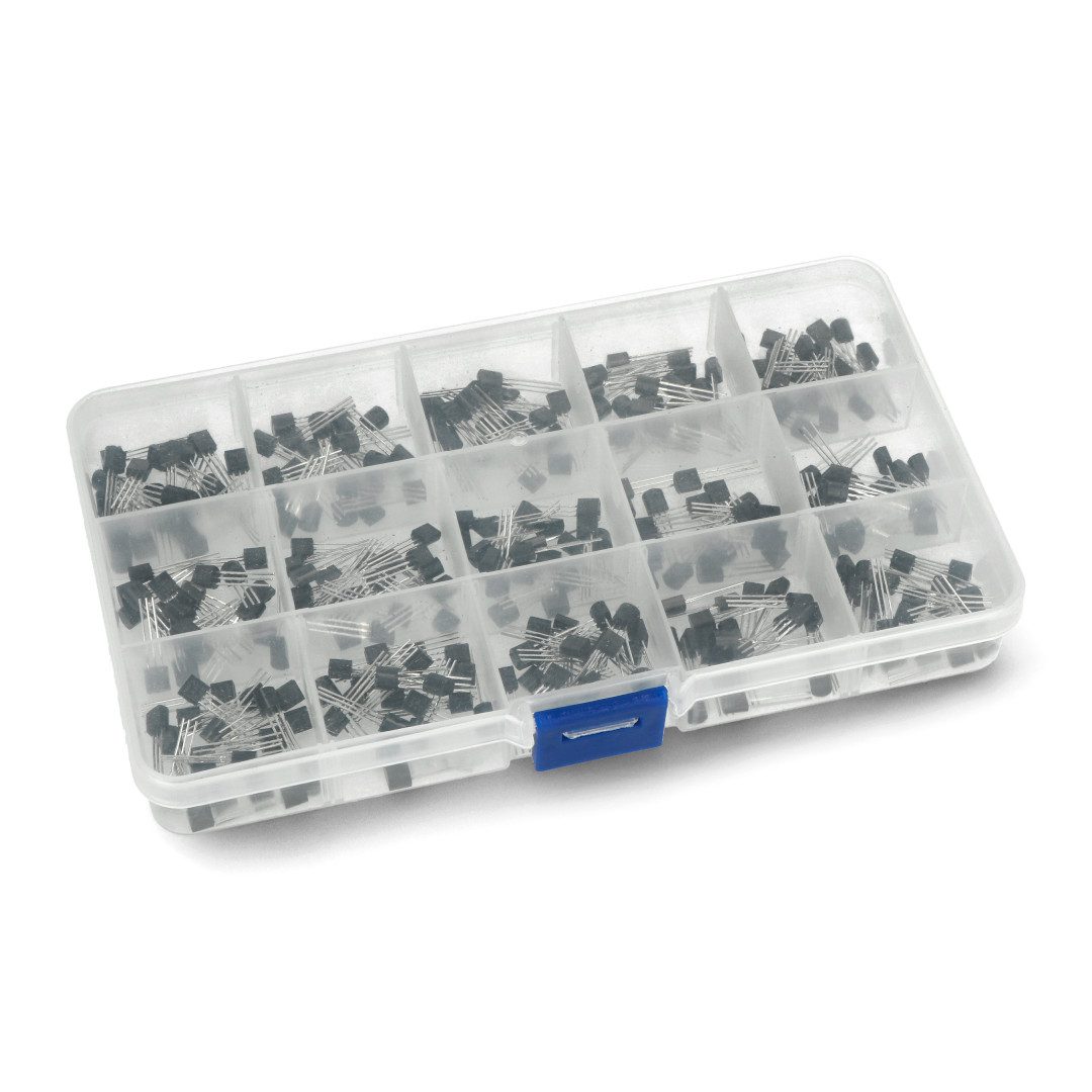
The TL431 allows the reference voltage to be precisely set from a few volts to tens of volts depending on the specific model, and the reference voltage to be stable under varying temperature and load conditions. It consumes a relatively small amount of current. It is immune to disturbances and fluctuations in supply voltage, making it a stable voltage source under various conditions. The TL431 can also act as a voltage comparator, that is, to compare the reference voltage with the input voltage. It is available in a variety of housings popular in microelectronics such as TO-92, TO-220, SO-8, and this allows easy integration into various circuits as a module.
Technical data and mode of operation
Using an external voltage divider, the TL431 can regulate voltages in the range of 2.495 to 36 V at currents of up to 100 mA. The typical initial deviation of the reference voltage from the nominal 2.495 V level is measured in millivolts, the maximum deviation in the worst case is measured in tens of millivolts. The circuit can directly control power transistors, and combinations of TL431 with power MOS transistors are used in high-performance linear regulators with very low droop. When Vref is below the threshold of 2,495 V, the output transistor is closed.
The residual cathode-anode current of the ICA feeding the front-end circuit is maintained within 100 and 200 μA. As Vref approaches the ICA threshold, it increases to 300-500 μA, but the output transistor remains closed. When the threshold is reached, the output transistor gently opens, and the ICA begins to rise at a rate of about 30 mA/V. When Vref exceeds the threshold by about 3 mV and ICA reaches 500-600 μA, the transconductance jumps sharply to 1. Above this point, the TL431 operates in normal high transconductance mode.
The current increases until the negative feedback loop connecting the cathode to the control input stabilizes the voltage at some point above the threshold. This point is the reference voltage of the entire regulator. Alternatively, the TL431 can operate without feedback as a voltage comparator or with positive feedback as a Schmitt trigger; in such applications, the ICA is limited only by the anode load and power supply capacitance.
The nominal reference voltage of 2.495V given in the specifications is tested in Zener mode at an ambient temperature of +25°C and ICA of 10mA. The threshold voltage and the limit between low and high transconductance modes are not specified and are not tested. The actual voltage held by a particular TL431 in a real application may be higher or lower than 2.495 V, depending on the starting bias of the particular IC, temperature and due to the output impedance.
TL431 - schematic diagram
The TL431 has one input, which is connected to a pull-up resistor (R1) and a load resistor (R2). This input is called the “anode” or “voltage input.” The output of the TL431 is called the “cathode.” This is the point from which the reference DC voltage is read, which is usually determined by the specific TL431 model. The fourth pin of the TL431 is called the “channel member.” It is powered by the supply voltage (Vcc) and is used to provide power for the circuit itself. In practice, the values of resistors R1 and R2 are selected to obtain the desired reference voltage at the TL431 output. By changing the values of these resistors, you can adjust the circuit’s reference voltage to suit your particular application.
TL431 - price, opinions
In terms of practice, a natural consideration of advantages and disadvantages can be carried out with reference to the aforementioned competitor,
Zener diode
.
Voltage stabilizers
are usually the cost of a few to a dozen zlotys in packs of 5 or 10. It’s a slightly more expensive option than Zener diodes (a few tens of pennies or a few zlotys) to use in THT projects, which is important for projects with limited budgets, but it’s more applicable to large-scale projects, as on a small scale the difference is not so significant. Stabilizers offer higher stability, provide a constant output voltage regardless of changes in supply voltage and load, are more effective in reducing output noise and have lower output noise compared to Zener diodes.
It is worth remembering that stabilizers generate more heat, which can be a problem in applications requiring high energy efficiency – some energy is lost as heat. Although they do not offer the same stability as stabilizers, they can be sufficient for some simple applications, such as limiting the voltage within a certain range. Reviews of the TL431 are generally positive especially among engineers and electronics hobbyists. The chip is recognized for its versatility from simple power supplies to regulator circuits, stable, precise reference voltage, ease of use, availability of enclosures, relatively low cost and good temperature stability. Because of these features, the TL431 has become a popular choice for electronic projects around the world.
How useful was this post?
Click on a star to rate it!
Average rating 0 / 5. Vote count: 0
No votes so far! Be the first to rate this post.