Table of Contents:
Manual switching on and off of outdoor lighting is cumbersome and in some situations even impossible. If street lighting is to fulfil its safety and ergonomic role properly, it should be controlled according to the actual light level (highly sensitive to cloudiness and time of year) and not according to a clock.
The same applies, for example, to the lighting of the garden, garage entrance or car park – wherever the light should be on continuously from dusk to dawn, a twilight sensor, also called a twilight automatic, is the ideal solution.
Twilight sensor – construction and principle of operation
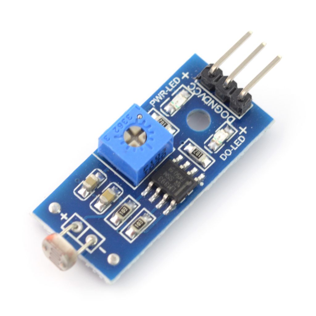
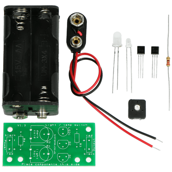
The construction of a twilight automatic device is based on three basic components – a proper light intensity sensor, an executive element serving for switching on the lighting and a control system whose task is to “decide” on switching on and off the control output depending on the level of ambient brightness.
The function of the sensor is almost always performed by a photoresistor – its very simple connection (usually in the form of a voltage divider in which the photoelement is connected in series with a constant resistor of appropriately selected value), high sensitivity and low cost mean that the majority of photoresistor applications are now twilight automatics.
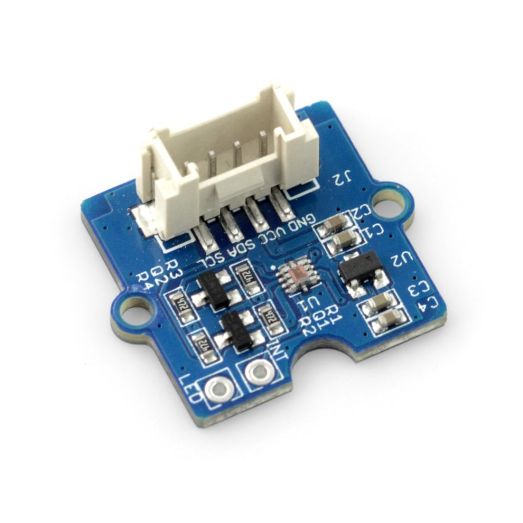
The control system can be built in a number of different ways – from simple analog comparators (based on discrete transistors or an integrated comparator as such) to more complex systems with a microcontroller and an analog-to-digital converter.
In the executive role usually works an electromagnetic relay – low price, simple principle of operation and ability to control even a large load makes that in the vast majority of devices relays still find their place. However, you can also find devices with a medium or high power transistor, switching the output supplying the lighting set – such a solution, however, works only in the case of DC systems, including mainly LED lighting applications.
Hysteresis and threshold adjustment
An extremely important aspect in every twilight sensor is the question of operation threshold – that is the intensity at which the output controlling the lamp (or lamps) is switched on or off. What is important, because of very slow ambient brightness changes caused by sunset and sunrise, the system with a single threshold above which the light is switched off (and below which it is switched on) would not work – characteristic random lighting flickering would be noticeable, caused by “uncertain” behaviour of the comparator system. That is why in every twilight automatic device it is necessary to apply hysteresis, i.e. some distance between the switch on threshold and the switch off threshold of the output – thanks to this small difference the comparator is resistant to slow changes of light intensity and “unequivocally” makes a decision about the output status.
Obviously, each photoresistor has a slightly different sensitivity, and the needs are also different in the case of each installation – therefore an absolutely necessary element in the case of the twilight automatic device is the system of operation thresholds adjustment (usually we talk about one single threshold, although in reality both thresholds are shifted, i.e. the output switching on and off limits, however without the change of the so-called hysteresis loop width). Usually the regulation is implemented in the form of assembly potentiometer, which allows smooth setting of the threshold after installing the sensor in the target place – only in such a situation one knows how to set the twilight sensor in order for it to properly fulfil its role
How to connect a twilight sensor?
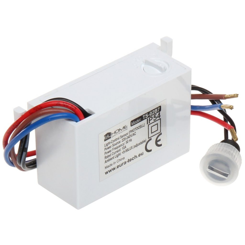
The issue of connecting the twilight sensor to the electrical installation requires separate discussion. In the majority of cases we deal with devices designed for mains powered lighting control, which is 230 V AC. In such cases we usually encounter solutions with three terminals – one of them (marked L) is to be connected to the mains phase wire, the second one (N) – to the neutral wire, and the third one is to connect one of the wires running from the bulb.
What is important, in majority, if not all dusk automatics, the bulb supply control is carried out from the phase side, that is why the second bulb wire should be connected (e.g. by means of a terminal block) to the neutral wire. Sometimes we may also encounter four-terminal solutions, in which separate pairs of contacts are intended for connection of the bulb and the mains supply. The last element which should be connected to the dusk switch is the photoelement itself. It is good to know that – unless the manufacturer has indicated other recommendations in the user’s manual – the order (polarity) of wires does not matter, because the photoresistor is a non-polar element.