Table of Contents:
Voltage and current values are basic parameters whose correct values ensure correct operation of devices. In this article, we present a sample circuit design for measuring voltage and current using an Arduino UNO R3 board together with an INA219 sensor.
For what purposes may current and voltage measurements be performed?
Every electrical appliance in your home must have an electricity supply in order to function. This includes your fridge, kettle, computer, vacuum cleaner and other appliances. In simple terms, the electricity meter makes billing measurements based on the energy consumed, which is derived from the electrical power consumed over a certain period of time. These measurements are made indirectly, because to calculate the power consumed, and then the energy, the meter’s measuring system also measures the supply voltage and the current consumed. To illustrate the principle of measuring current and voltage in a simple way, we will build a simple circuit in which the current consumed by the LED is supplied with voltage from the Arduino board.
Current and voltage measurement with Arduino – hardware requirements
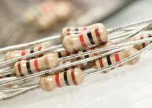
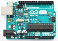
To complete this project, you will need to use an Arduino UNO R3 board and the INA219 sensor module, which is Arduino-compatible and can measure electrical voltage and current. The INA219 module communicates with the Arduino board via the I2C interface. You will also need a LED (e.g. red), a 470Ω resistor with a 5% tolerance and a contact board with connection wires. To program the Arduino, we will need the standard Arduino IDE environment, which can be downloaded for free from the manufacturer’s website.
Checking the connections accuracy
Before we can make any measurements, we need to check that the INA219 sensor is properly communicating with the Arduino board via the I2C bus. Configuring the sensor’s communication with the Arduino can be difficult and time consuming, but as with many other modules, Adafruit Industries has developed a dedicated library that can be downloaded from the GitHub repository at the following address:
https://github.com/adafruit/Adafruit_INA219
After downloading and unzipping all the files, rename the folder to Adafruit_INA219 and place the folder in the library folder of your Arduino folder (or create a folder for this library if you haven’t already). You can then test the following sketch (the program code below provides explanations):
					#include <Wire.h>
#include <Adafruit_INA219.h>
Adafruit_INA219 ina219; //Initialisation of INA219 sensor library
void setup() //initial program settings
{
 uint32_t currentFrequency; //variable type declaration for current frequency
 Serial.begin(9600); //launch of serial transmission
 Serial.println("Communication test with INA219 ..."); // communication test with INA219
 ina219.begin();
}
void loop() //the main programme loop
{
 float shunt_voltage = 0; //declaration of the type of variable for the voltage to be measured on a shunt
 shunt_voltage = ina219.getShuntVoltage_mV();
 Serial.print("Shunt Voltage: "); Serial.print(shunt_voltage); Serial.println(" mV");
 Serial.println("); //display of voltage measurement result
delay(100); //next measuring cycle in 100ms
}
After uploading the above program, we can observe the messages on the serial port monitor. In this case, the LED was not turned on, so the shunt voltage reading should be 0mV.
Complete programme
After checking that the sensor is working properly, we can load a complete program that will measure the current and power consumption of the LED. To do this, apply a voltage to the LED from digital pin “D2”, to which the LED is connected. A complete program taking these measurements into account will be of the following form;
					#include <Wire.h>
#include <Adafruit_INA219.h>
Adafruit_INA219 ina219;
void setup()
{
 uint32_t currentFrequency;
 Serial.begin(9600);
 Serial.println("Voltage and current measurement with INA219 sensor ...");
 ina219.begin();
 pinMode(2,OUTPUT);
}
void loop()
{
 digitalWrite(2,HIGH);
 float shunt_voltage = 0;
 float voltage1 = 0;
 float current = 0;
 float load_voltage = 0;
 float power = 0;
 shunt_voltage = ina219.getShuntVoltage_mV();
 voltage1= ina219.getVoltage1_V();
 current = ina219.getCurrent_mA();
 load_voltage = voltage1+ (shunt_voltage / 1000);
 power = current * load_voltage;
 Serial.print("Voltage1: "); Serial.print(voltage1); Serial.println(" V");
 Serial.print("Shunt Voltage: "); Serial.print(shunt_voltage); Serial.println(" mV");
 Serial.print("Load Voltage: "); Serial.print(load_voltage); Serial.println(" V");
 Serial.print("Current: "); Serial.print(current); Serial.println(" mA");
 Serial.print("Power: "); Serial.print(power); Serial.println(" mW");
 Serial.println(");
 delay(1000); // next measuring cycle in 1s
}
Typically, the power consumption of an LED should be around 10mW. However, this value may vary depending on what colour LED we use in our project, as a red LED will draw a different current than a yellow LED. The value of the current drawn will also depend on the value of the resistance of the series resistor. Do not connect the LED without a resistor – it may damage the LED and even the Arduino board.
How useful was this post?
Click on a star to rate it!
Average rating 0 / 5. Vote count: 0
No votes so far! Be the first to rate this post.


