Table of Contents:
In the previous article we installed the server system and software and created and configured a database. Now we want to create the layout and upload the files of the page to be placed on RPi. We will be able to connect to it while we are on the local network.
Before we continue, please check out Part 1 of our tutorial (see the link below). There you will find a complete list of the elements required to build your system.
Layout creation
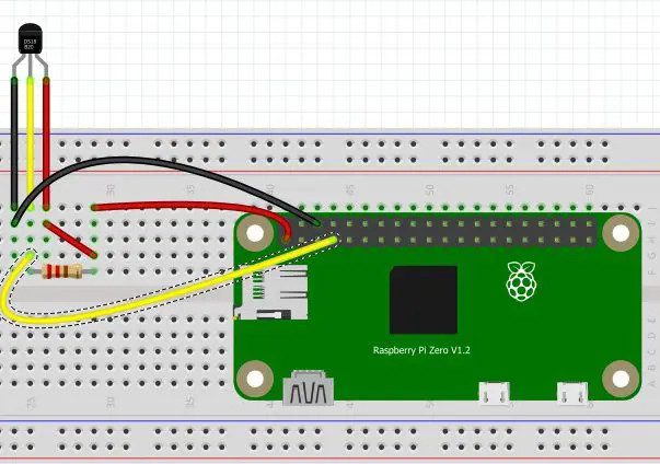
Let’s start by setting up a system with which we will implement the project. In order to do this, we will use the Grove Base Hut for RPi Zero, 4 Grove relays, wires connecting the Base Hut board with the relays, the DS18B20 sensor, a small contact plate, some wires, a resistor of 4.7k Ohm and the already configured Raspberry Pi with gold pins soldered on before.
The relays are connected by cables to the connectors marked D16, PWM, I2C and UART. Connecting the relays to the shield should not be a problem.
Now we have to connect the temperature sensor. Pull out 3.3 V, GND and pin 4 of RPi to the contact plate. Now connect the DS18B20 to the contact plate, and connect the wires from the sensor to the following pins:
- red 3.3 V – VCC pin
- black or green GND – GND pin
- white or yellow to pin 4 – data pin
In addition to the connection between the data pin and the VCC pin described above, we also have to connect a 4.7k Ohm resistor. The connection between your Raspberry and the sensor should look like this:
Reading data from the DS18B20 sensor
Before we move on to controlling the relays, let’s learn how to read data from the temperature sensor. Let’s start by switching on the OneWire interface, thanks to which we will be able to read the result from the sensor. We need to enter the code below into the terminal:
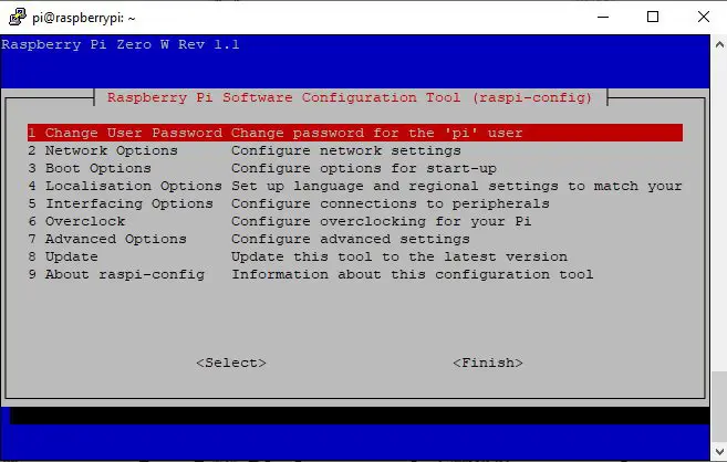
We will now open the Raspberry settings window. Jump to item number 5, i.e. Interfacing Options, and click Enter. After moving to the next window, use the arrows to jump to position 7, i.e. One-Wire, and press Enter again. We confirm the operation twice. After the entire procedure, RPi should restart, which will cause a simultaneous restart of services and interfaces, including our OneWire.
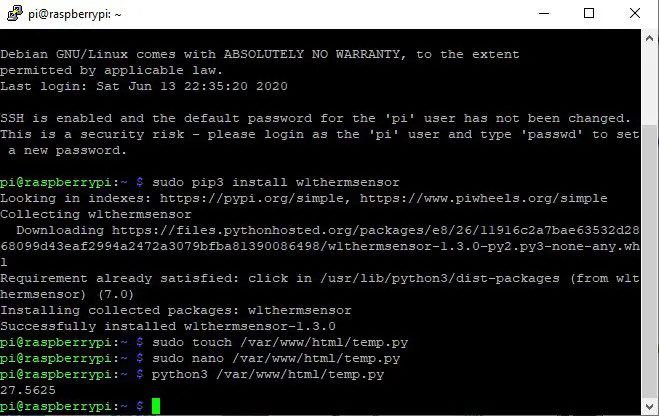
Now we want to simplify the reading from the sensor. To make it easier, we will install a library that allows us to read the measurement result with one command. To install the library in the terminal, type:
sudo pip3 install w1thermsensor
Once the library is successfully installed, let’s create a program in the folder that stores the page files. It allows you to read from the sensor at any time. The first operation is to create an empty file. We create it with the command:
sudo touch /var/www/html/temp.py
Now we have to enter the program content into the file. To do this we have to open it with the command:
sudo nano /var/www/html/temp.py
Confirm with Enter to open a text editor where we have to paste the following code (in the terminal, we paste by clicking the right mouse button):
import w1thermsensor
czujnik = w1thermsensor.W1ThermSensor()
temperatura = czujnik.get_temperature()
print(temperatura)
Now we close the text editor with the shortcut CTRL +X and confirm the saving. We will now check if the program works correctly.
Type in the console:
python3 /var/www/html/temp.py
Then we should see the ambient temperature as below:
Testing the efficiency of relays
After we have checked and configured the temperature sensor, we can continue with the relay check. Since we use the relays in the form of prefabricated modules, there is no risk of error from the outset due to incorrect connection of the elements. All that remains is to check whether the RPi switches the relay on after it has received the specified command. Let’s start with the relay connected to pin 16. To enable it, we will use the wiringPi library, which allows you to set the state of a specific GPIO pin in your Raspberry.
The commands are very simple and look like this:
gpio -g write 16 1
To make it easier, let’s also brush up on the arrangement of the pins on RPi according to the processor numbering. In case of any modification of the program (e.g. to add functions) we will know the pin assignment. The following figure shows the arrangement of the pins:

To make it easier, let’s also brush up on the arrangement of the pins on RPi according to the processor numbering. In case of any modification of the program (e.g. to add functions) we will know the pin assignment. The following figure shows the arrangement of the pins:
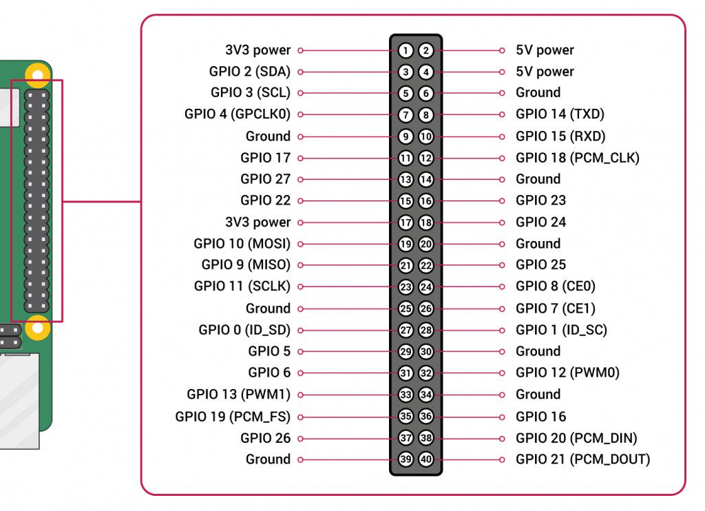
Once we know the arrangement of the pins and we know how to change their state, we can check if the method works. Let’s enter the command shown above. Now we should hear the relay make a “click” sound – to make sure we can check with a multimeter if there is a short circuit between the relay pins. If so, we have created a fully functional configuration!
Uploading the website that manages our smart home system to the server
We have already configured our minicomputer and server; we have checked if we can read the temperature and switch on the relay-controlled devices. Everything is working perfectly, so we can continue with the creation of a page that will allow us to manage the whole system. Of course the site will be written in HTML, with some scripts in PHP, and its appearance will be determined by CSS styles. The website is not complicated, but requires knowledge at a slightly higher level than that of beginners. We will publish it without going into individual sections, but if you are interested, feel free to review the code for learning purposes. In order for the page to be on our server, we must first create the file “index.php” in the folder responsible for the pages on the local server. It is called “/ var / www / html”. Once the page file is set in this directory, it will be displayed when we enter the server.
To check what is in the folder where the page files are stored, type the following in the terminal:
ls /var/www/html
If there is a file “index.html” in the folder “/ var / www / html”, we have to delete it so that it does not conflict with our new page file. We will use the command below to delete this file:
sudo rm -r /var/www/html/index.html
If we now enter the command that displays the contents of the directory, the file “index.html” should not appear, because it simply no longer exists. For the whole system to work, a new page is needed, so we create a file using the command:
sudo touch /var/www/html/index.php
After creating the file, we need to copy the index.php file from the GitHub directory and paste it into the file on our Raspberry, which we open with the command:
sudo nano /var/www/html/index.php
We paste the whole content of the file with the right mouse button and close the file with the shortcut CTRL+X. The page file is ready, but if we open the page now, it will look like this on the server. Not too nice, is it? So let’s add styles! This operation is very similar to adding a new page file. At the very beginning we create the file “styl1.css” (in this case we do not need to check if such a file exists, CSS files are not installed by default with APACHE ). To create the file, we use the “touch” function, as described below:
sudo touch /var/www/html/styl1.css
And we open the file using:
sudo nano /var/www/html/styl1.css
After you open the file, paste the contents of the file with the same name from the GitHub repository. Once it’s pasted, use CTRL+X and confirm. Now let’s do a quick restart of the server:
sudo service apache2 restart
After the restart we can run the page. To do this, enter the local address of your Raspberry in the browser and type “/index.php” at the end (the page should be displayed correctly even without the file addressing extension, but it is best to be on the safe side!). In my case, the address looks like this:
“192.168.1.35/index.php”,
And you’ll see the page.
You see the difference, do not you? Now let’s check if the relays turn on by clicking on the button on the website. If so, we can be proud of ourselves! In the next article we will create the PCB layout and hide it in a 3D printed casing of our own design.
How useful was this post?
Click on a star to rate it!
Average rating 0 / 5. Vote count: 0
No votes so far! Be the first to rate this post.