Table of Contents:
Motors can be controlled in many different ways. And when we wish to control motors with a controller, we need a proper motor controller.
In robotics, we have different types of motors. These are:
What is a motor driver, or motor controller?
A motor controller-sometimes called a driver-takes the low-current signals generated by the controller and converts them into higher-current signals that drive the motor. Essentially, the motor driver acts as an interface between the motor and the control circuit. Motor controllers allow you to control a much larger load from a small signal. They can handle high voltage and current.
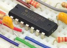
A motor driver consists of an integrated circuit or transistors that can handle high power. Motor controller ICs are current amplifier ICs that act as a bridge between the controller and the motor. The circuitry contained in the chip is responsible for the connections to the H-bridge that controls the motor. Different chips offer different interfaces – some of the well-known motor driver chips are L293D and L298N.
H-bridge
The H-bridge is a quite simple circuit. Its name derives from the typical graphical representation of the circuit, which resembles printed capital letter H. It is built with 4 contacts (semiconductor elements, often MOSFET or IGBT transistors, or mechanical ones). When contacts S1 and S4 are closed and S2 and S3 are open, voltage will be applied to the motor and it will start to rotate. By opening contacts S1 and S4 and closing S2 and S3, we can change the direction of current flow, thereby changing the direction of rotation of the rotor.

How to choose a motor controller?
There are several criteria to consider when selecting a component for projects.
Motor compatibility
The first thing to look at when choosing a motor controller is its list of compatible motors. Most motor controllers are compatible with brushless DC motors, geared motors used in industry, agriculture and many craft industries, and stepper motors, but some motor controllers are only compatible for angular-based motors such as servos. So be sure to choose a controller that is appropriate for the motor you have.
Current and voltage
Next, we got to take a look at voltage and current capacity. Drivers are usually available in a wide range of voltages. The range varies from a few volts to as much as 50 volts. We have an equally wide choice when it comes to current capacity – from values lower than 1 A to dozens. All you have to do is to narrow down the parameter while search.
Interface
The motor controller interface must fit the intended application. Many of them offer compatibility with Arduino and low-power TTL (transistor-transistor logic) inputs. However, if you want to control the motor wirelessly, such as via Bluetooth, then remote controllers are worth considering. The number of channels is no less important – for 16 motors with 16 external signals, you will need a 16-channel controller, of course with an appropriate voltage parameter.
Electrical resistance
The current in the motor driver IC flows through the resistance in the on state of the bridge transistor. A large current will therefore lead to power dissipation. The power dissipation can be expressed as:
P = I2R
where P is the power, I is the current, and R is the on-state resistance. Power dissipation is noticeable in the form of heat. A driver IC operating at its peak current capacity increases its internal temperature very quickly, which can cause overheating and shutdown – known as thermal shutdown. Knowing this, therefore, choose an IC with high current capacity, and if there is any chance that the IC will overheat, then it is best to use cooling in the form of a heat sink. If there is not enough space on the PCB, then you need to choose an IC with lower on-state resistance to minimize power dissipation.
How useful was this post?
Click on a star to rate it!
Average rating 0 / 5. Vote count: 0
No votes so far! Be the first to rate this post.


