 Specification
- Supply voltage of the logic part: 3.0 V to 5.5 V
- Measuring range: from - 31 A to 31 A
- Current consumption of the logic part: 4 mA
- Sensitivity for power supply of 3.3 V: 0,045 V/A
- Bandwidth: 100 kHz
- Operating temperature: -40 °C to 125 °C
- Module weight: 1 g (without connectors)
- Dimensions: 18 x 20.5 mm
Description
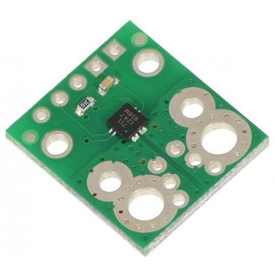
The module consists of a printed circuit board made for the system Allegro ACS711. The sensor operates based on the Hall effect. The chip can be powered from a voltage in the range: 3 V to 5.5 V.
Basic module features:
- The chip is designed for current flowing in both directions (from -31A to 31A)
- The modulewithstands current surges up to 100 A for 100 ms
- Due to the low resistance of the system (0.6 mΩ) and channeling, the power losses are very small.
- Through the use of Hall effect, the current paths are isolated from the logic part.
- The bandwidth is 100 kHz
- The FAULT pin informsabout exceeding the range of 31 A
- Operating temperature: -40 °C to 125 °C
Connection method
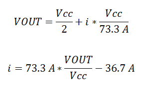
The sensor requires a supply voltage in the range from 3 V to 5.5 V, connected to the pins designated as VCC (+) and GND (ground). The output is a voltage signal proportional to the intensity of the measured current. When the voltage VCC is equal to 5 V, the output is centered on the half, that is 2.5 V. The output value increases by 45 mV at 1 A when the strength of the measured current is positive, otherwise, it decreases.
Formulae allowing to calculate the output values:

The FAULT pin is in the high status by default. It reaches a low status when the measured current exceeds the range of ±31 A. The only way to reset the FAULT flag is disconnecting and then re-connecting the power supply - VCC.
|
Attention! The system is designed to work with voltages up to 30 V. Higher values can pernamently damage the module. |
Scheme
The module includes the passive components necessary for proper operation of the ACS711 sensor.
Useful links |


