 Specification
- Supply voltage of the logic part: 3.0 V to 5.5 V
- Measuring range: from 15 A to 15 A
- Current consumption of the logic part: 4 mA
- Sensitivity for power supply of 3.3 V: 0,090 V/A
- Bandwidth: 100 kHz
- Operating temperature: -40 °C to 125 °C
- Module weight: 1 g (without connectors)
- Dimensions: 18 x 20.5 mm
Description
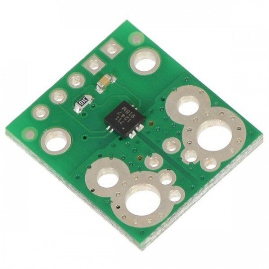
The module consists of a printed circuit board made for the system AllegroACS711KEXLT-15AB-T. The sensor operates based on the Hall effect. The chip can be powered from a voltage in the range: 3 V to 5.5 V.
Main features of the module:
- The system is designed for current flowing in both directions (from -15A to 15A)
- The modulewithstands the current surges of up to 100 A for 100 MS
- Due to thelowresistance of the system (0.6 mΩ) and channeling, the power losses are very small.
- Through the use of Hall effect, the current paths are isolated from the logic part.
- The bandwidth is 100 kHz
- The FAULT pin which informsabout exceeding the range of 15 A
- Operating temperature: -40 °C to 125 °C
Connection method
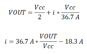
The sensor requires a supply voltage in the range from 3 V to 5.5 V, connected to the pins designated as VCC (+) and GND (ground). The output is a voltage signal proportional to the intensity of the measured current. When the voltage VCC is equal to 3.3 V, the output is centered on the half, that is 1.65 V. The output value increases by 90 mV at 1 A when the strength of the measured current is positive, otherwise, it decreases.
Formulae allowing to calculate the output values:

The FAULT pin is by default in the high status. It reaches a low status when the value of the measured current exceeds the range of ±15 A. The only way to reset the Fault flag, is to disable and then re-connect the - VCC power supply.
|
Attention! The system is designed to work with voltages below 30 V. Higher values can pernamently damage the module. |
Scheme
The module includes the passive components which are necessary for proper operation of the ACS711 sensor.
Useful links |


