Specification
- Supply voltage: 4.5 V to 36 V
- Continuous output current per channel: 1.7 A
- The maximum short-term current per channel: 2.5 A
- PWM frequency: up to 50 kHz
- Protection from incorrect power supply attachment
- Designed for Arduino connectors
- The possibility of Raspberry powering using an additional regulator (not included)
- The libraryforArduino facilitating maintenance of the module
- Dimensions: 51 x 24 mm
- Weight: 4.8 g (without connectors)
Description
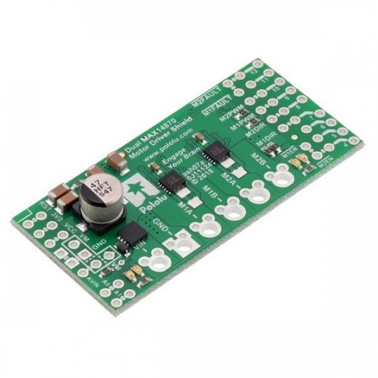
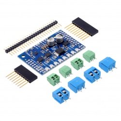
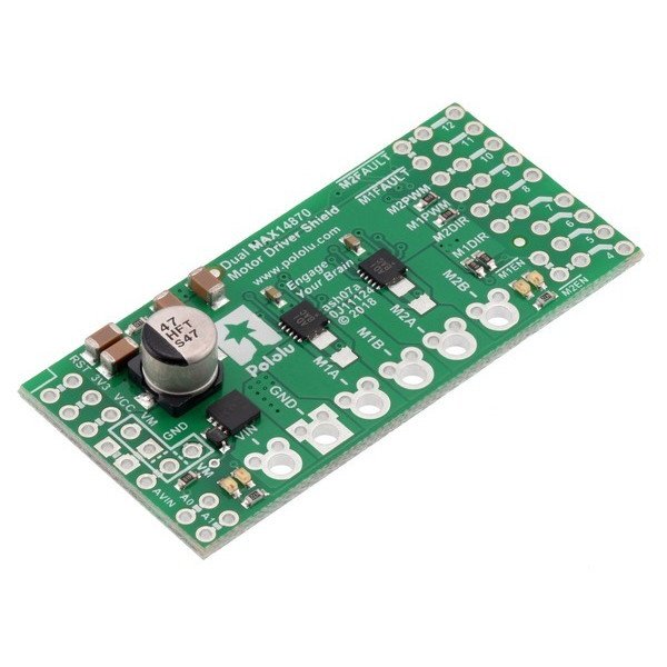
The module is based on two MAX14870 systemslet you control the motors with a supply voltage of up to 36 V and a continuous current consumption of up to 1.7 A. The driver withstands ale the seconds of jumping current up to 2.5 A. The speed of rotation can be controlled by the signalPWM.
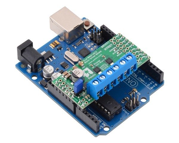
In conjunction withArduino, using a specially preparedlibrary,you can easily control the speed and direction of rotation of two DC motors. Shape and pins of the board allow for direct connection with minicomputer, as shown on the pictures. The system uses 16 pins.
|
The product is compatible with Arduino The manufacturer provides alibrary for users ofArduino. |
Connection
The following table shows which pins of Arduino are used by driver of motors:
|
Pin RPi GPIO |
Pin of the driver |
Description |
|---|---|---|
| 4 | EN |
By default in the low state, it indicates the disabled outputs of the motors. To run the driver, you must specify the high status. |
| 12 | FAULT |
The error output. By default in the high state. It indicates excessive current or temperature. |
| 9 | Motor 1 PWM |
The PWM input to control the rotation speed of the motor. The maximum PWM frequency is 50 kHz. |
| 10 | Motor 2 PWM |
The PWM inputs to control the rotation speed of the engine. The maximum PWM frequency is 50 kHz. |
| 7 | Motor 1 DIR |
Pin to select the direction of rotation. In low state, the current flows from output A to B. In high state, from B to A. |
| 8 | Motor 2 DIR | Pin to select the direction of rotation. In low state, the current flows from output A to B. In high state, from B to A. |
Modes of operation
The table shows the operation modes depending on the inputs:
| EN | DIR | PWM | MxA | MxB | Work mode |
|---|---|---|---|---|---|
| 0 | 0 | PWM | PWM (H/L) | L | Forward rotation at a certain speed PWM %. |
| 0 | 1 | PWM | L | PWM (H/L) | Back rotation at a certain speed PWM %. |
| 1 | x | 0 | L |
L |
Braking (connected to ground). |
| 1 | x | x | Z | Z | Disabled outputs. |
Additional limit of current
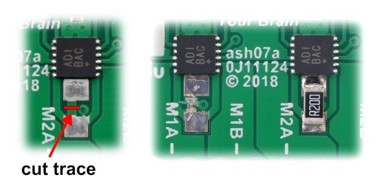
System MAX14870 has SNS input that can be used as an automatic current limiter. By default, it is connected to GND for both systems. To enable the limit , you must first cut the trace between the pins of the resistors 1206. Then, to these pins, you should connect the appropriate resistor 1206.
Power of Arduino
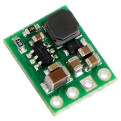
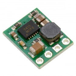
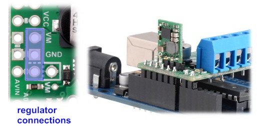
The device provides power to the minicomputer from the input voltage of the module. Do not connect the power supply to the Arduino, since it threatens to damage the boards. When the input voltage of the motors is suitable for Arduino, you should solder a jumper AVIN=VM" and use the blue screw connections, so the power supply was far from the Arduino. As the board can work with voltages much higher than the microcontroller, it is very important to use this jumper only if the voltage of motors and of Arduino, is equal. If the voltage is higher, we recommend you to usethe converter D24V10F5in a specially prepared holes.
Useful links |
