


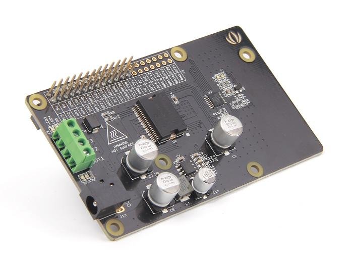
The Raspberry Pi Motor Driver Board v1.0 is a motor controller based on the Freescale MC33932 H double bridge IC that can control inductive loads up to 5.0 A per single bridge.It allows you to control two DC motors with Raspberry Pi B/B+/A+ and Pi 2 Model B, independently controlling their speed and direction.
The motor controller supports a very wide input voltage range of 6V~28V. In addition, the onboard DC/DC converter also supports a very wide input voltage range and supplies the Raspberry Pi with 5V at a maximum current of 1000mA. One power supply is therefore sufficient both to drive the motors and to power the Raspberry Pi.
| Buy it now |
Characteristics
- Output short circuit protection (VPWR or GND)
- Overcurrent limitation (regulation) by internal PWM with fixed shutdown time
- Reduction of the temperature-dependent current limit value
- Compatible with Raspberry Pi
Technical Specification
| Feature | Min | Typical | Max | Unit |
|---|---|---|---|---|
| Operating voltage | 6 | / | 28 | VDC |
| DC/DC output | / | 5 V / 1000 mA | / | |
| Output (for each channel) | / | 2 (continuous operation) | 5 (top) | A |
| PWM frequency | / | / | 11 | kHz |
| Output load range | 0 | / | 100 | % |
| Logical input voltage | -0.3 | / | 7 | V |
| Working temperature | -40 | / | 120 | °C |
| Dimensions | 91 x 56.15 x 32 | mm | ||
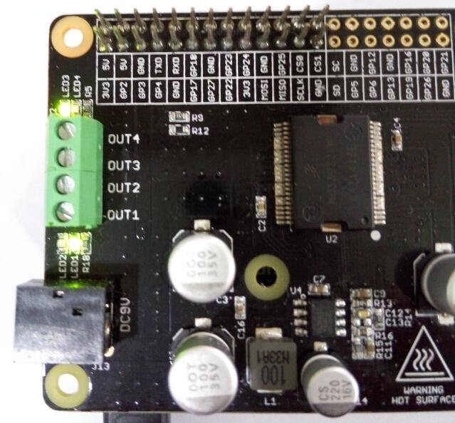
Equipment overview
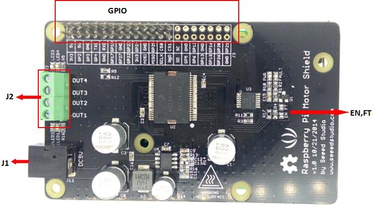
- J1: input connector.
- J2: motor controller output connector.
- EN,FT: Jumpers for EN control and fault detection. If the EN jumper is shorted, the EN signal will be mapped to pin D4, you can control the bridge output H or reset the fault via pin D4. When the FT jumper is shorted, the error signal is mapped to pin D3 and the error can be read from the ether of pin D3.
- IO: jumper to select logical voltage level.
- Power supply: The overlay is supplied by J1 (DC input connector). The input voltage range can be set to 6Vdc ~ 28Vdc. The DC/DC converter can convert the DC input voltage to 5Vdc output voltage to supply logic.The DC/DC converter can also power the microcontroller board (Arduino/Seeeduino) from the "5V" pin at a maximum current of 100mA.
- Interface silnika:Out1 and Out 2 (Out 3 and Out 4) connect Motor A(B) for DC motor.
|
Note Do not touch the H-bridge chip or PCB during operation. Their temperature can be as high as 100 degrees when operating at full load. |
Use
This demo uses the Raspberry Pi B to show how the Raspberry Pi Motor Driver Board v1.0 can be used to control the DC motor forward and reverse.
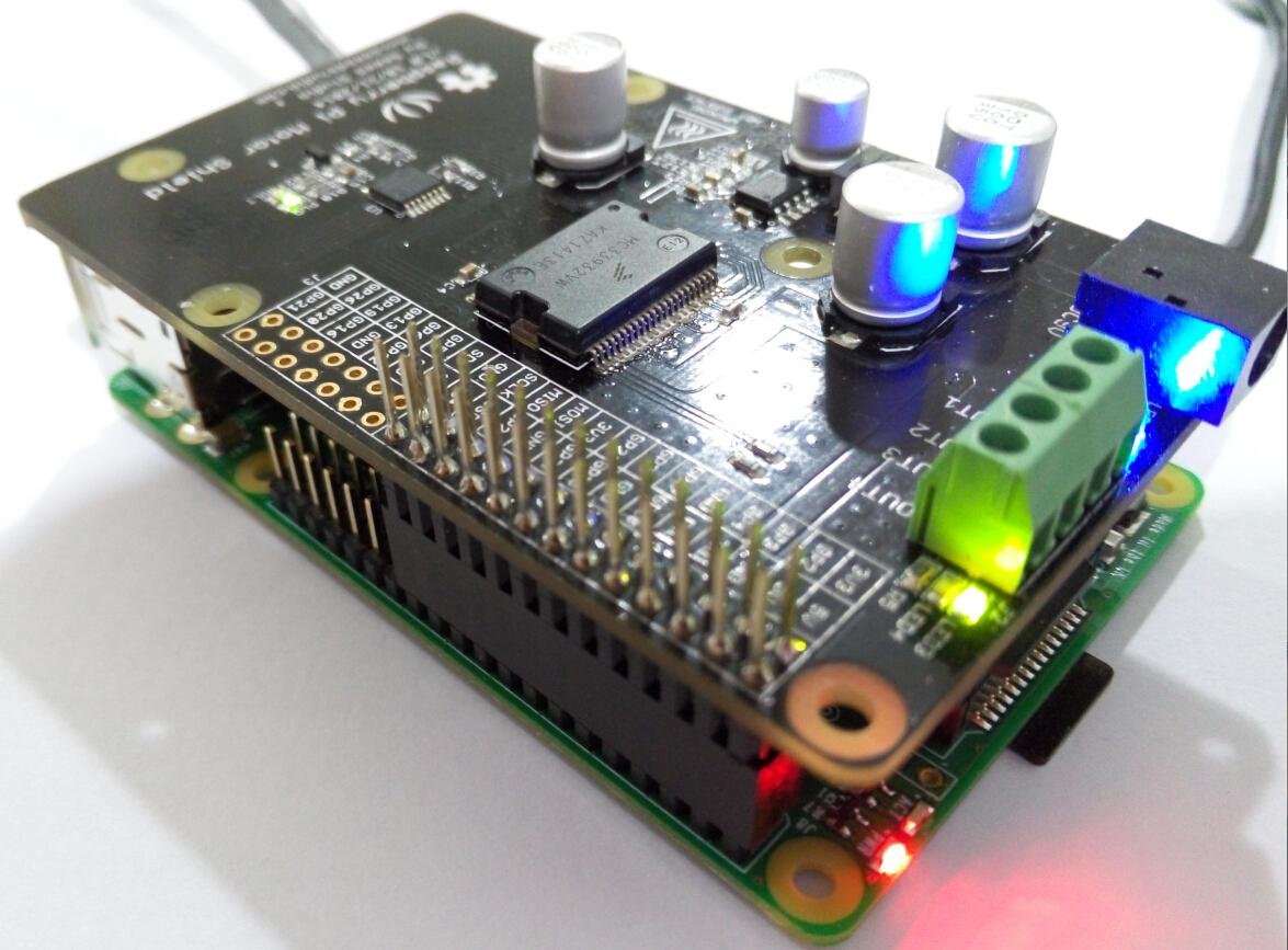
Hardware installation
- Raspberry Pi B and Raspberry Pi Motor Driver Board v1.0
- Mounting the equipment as shown in the picture
Connect to the network and to the power supply.
Software
#!/usr/bin/python
import RPi.GPIO as GPIO
import time
import signal

from PiSoftPwm import *

#print 'Go1...'
#frequency = 1.0 / self.sc_1.GetValue()
#speed = self.sc_2.GetValue()

Class Motor():
    def __init__(self):
    # MC33932 pins
        self.PWMA = 25
        self.PWMB = 22
        self._IN1 = 23
        self._IN2 = 24
        self._IN3 = 17
        self._IN4 = 27

    # Initialize PWMA PWMB
        GPIO.setmode(GPIO.BCM)
        GPIO.setup(self.PWMA, GPIO.OUT)
        GPIO.setup(self.PWMB, GPIO.OUT)
        GPIO.output(self.PWMA, True)
        GPIO.output(self.PWMB, True)

    # Initialize PWM outputs
        self.OUT_1 = PiSoftPwm(0.1, 100, self._IN1, GPIO.BCM)
        self.OUT_2 = PiSoftPwm(0.1, 100, self._IN2, GPIO.BCM)
        self.OUT_3 = PiSoftPwm(0.1, 100, self._IN3, GPIO.BCM)
        self.OUT_4 = PiSoftPwm(0.1, 100, self._IN4, GPIO.BCM)

        # Close pwm output
        self.OUT_1.start(0)
        self.OUT_2.start(0)
        self.OUT_3.start(0)
        self.OUT_4.start(0)

        self.frequency = 0.01
        self.duty = 60

    def Setting(self, frequency, duty):
        self.frequency = frequency
        self.duty = duty

    def Go_1(self):
        self.OUT_1.changeBaseTime(self.frequency)
        self.OUT_2.changeBaseTime(self.frequency)
        self.OUT_1.changeNbSlicesOn(self.duty)
        self.OUT_2.changeNbSlicesOn(0)

    def Back_1(self):
        self.OUT_1.changeBaseTime(self.frequency)
        self.OUT_2.changeBaseTime(self.frequency)
        self.OUT_1.changeNbSlicesOn(0)
        self.OUT_2.changeNbSlicesOn(self.duty)

    def Go_2(self):
        self.OUT_3.changeBaseTime(self.frequency)
        self.OUT_4.changeBaseTime(self.frequency)
        self.OUT_3.changeNbSlicesOn(0)
        self.OUT_4.changeNbSlicesOn(self.duty)

    def Back_2(self):
        self.OUT_3.changeBaseTime(self.frequency)
        self.OUT_4.changeBaseTime(self.frequency)
        self.OUT_3.changeNbSlicesOn(self.duty)
        self.OUT_4.changeNbSlicesOn(0)

    def Stop(self):
        self.OUT_1.changeNbSlicesOn(0)
        self.OUT_2.changeNbSlicesOn(0)
        self.OUT_3.changeNbSlicesOn(0)
        self.OUT_4.changeNbSlicesOn(0)

if __name__==="__main__":
    motor=Motor()
    # Called on process interruption. Set all pins to "Input" default mode.
    def endProcess(signalnum = None, handler = None):
        motor.OUT_1.stop()
        motor.OUT_2.stop()
        motor.OUT_3.stop()
        motor.OUT_4.stop()
        motor.GPIO.cleanup()
        exit(0)

    # Prepare handlers for process exit
    signal.signal(signal.SIGTERM, endProcess)
    signal.signal(signal.SIGINT, endProcess)
    signal.signal(signal.SIGHUP, endProcess)
    signal.signal (signal.SIGQUIT, endProcess)

    motor.Setting(0.01, 60)
    print 'motor start...'
    while True:
        print 'motor A turning forward...'
        motor.Go_1()
        time.sleep(1)
        print 'motor A turning backward...'
        motor.Back_1()
        time.sleep(1)
        print 'motor A stop...'
        motor.Stop()
        time.sleep(1)
        print 'motor B turning forward...'
        motor.Go_2()
        time.sleep(1)
        print 'motor B turning backward...'
        motor.Back_2()
        time.sleep(1)
        print 'motor B stop...'
        motor.Stop()
        time.sleep(1)
- Turn on this program. LED1, LED2 on Raspberry Pi Motor Driver Board v1.0 will light up alternately; LED3, LED4 will also light up alternately.
This means that Out 1 and Out 2 (Out 3 and Out 4) connect Motor A(B) forward and backward.
- The phenomenon is as follows:
Serial console:
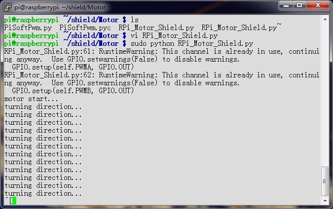
Raspberry Pi Motor Driver Board v1.0: The green LED and the blue LED will light up alternately.