


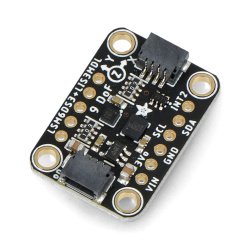


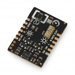


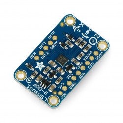


Sensor to measure magnetic field in three axes in the range from ±4 gauss to ±16 gauss. The supply voltage is from 2.5 V to 5.5 V, sensor is characterized by small size, low energy consumption and usage simplicity. It communicates via the I2C or SPI bus.
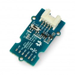
Sensor, compass for measuring a magnetic field in three axes. It is characterized by small size, low energy consumption and usage simplicity. It communicates via the I2C or SPI bus. Thanks to the integrated converters, the sensor operates with a voltage of 3.3 V and 5 V.
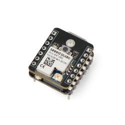
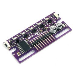
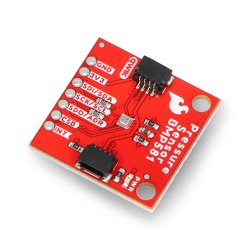
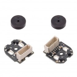
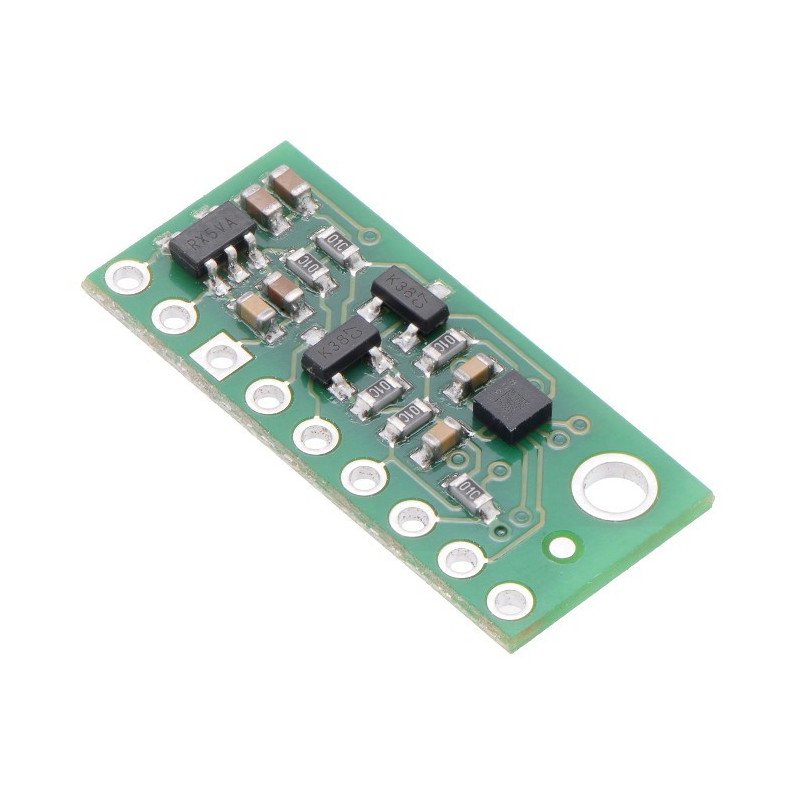
For communication with the central unit, the popular I2C bus (TWI) or SPI bus is used. The module has necessary for the correct operation of the system, passive elements. Pins are the solder fields for self-assembly of goldpin connectors (included) for connecting the sensor viawiresor to directly attach to thebreadboard.

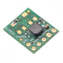
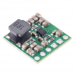
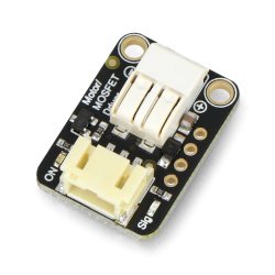
The module has a built-in step-down converter, whereby it is possible to work with voltages from 2.5 V to 5.5 V. The regulator's output is available on the pin VDD and can power external systems with the current of up to 150 mA
|
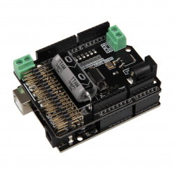
The product is compatible with Arduino The manufacturer has prepareda libraryfor users ofArduino on the GitHub. |
The sensor has 9 pins for mounting the connectors ofgoldpintype - pitch of 2.54 mm (included). SCL and SDA pins tolerate voltage higher than 3.3 V, as they are attached to the voltage converter. The remaining pins are not connected and do not tolerate 5 V voltages, therefore they must be connected through an external logic level converter.

| Name |
Description |
|---|---|
| VDD | Regulated output of 3.3 V, max. 150 mA. |
| VIN |
The power supply of the system is from 2.5 V to 5.5 V. The converter aligns the SCL and SDA pins for the I2C and SPI bus to that level. |
| GND | The ground of the system. |
| SDA / SDI / SDO | Data line for I2C and input line for SPI. High status is equal to VIN, low status is 0 V. |
| SCL / SPC | Clock line for I2C and SPI. High status is equal to VIN, low status is 0 V. |
| SDO / SA1 | Data output line for SPI. High status is equal to VDD, low status is 0 V. It's working with the voltage of 3.3 V. |
| CS | The choice of the data bus. High status (VDD) turns on the I2C communication (set by default). Low status turns on the SPI bus. |
| DRDY | Ready data indicator. High status informs that the data is ready for reading. It works with a voltage of 3.3 V. |
| INT | Programmable interrupts. It works with a voltage of 3.3 V. The details inthe documentation. |
Useful links |
| Niebezpieczne | Component |
| Package width | 7.5 cm |
| Package height | 0.6 cm |
| Package depth | 8.5 cm |
| Package weight | 0.003 kg |
Be the first to ask a question about this product!
Product Information
The product is a component intended for further assembly/prototyping. It does not constitute a standalone finished product within the meaning of product safety regulations.
Dane GPSR
Country of Origin: United States
Manufacturer Contact Details: Pololu Corporation 920 Pilot Rd. Las Vegas, NV 89119 USA [email protected]
EU Marketer Contact Details: BOTLAND B. DERKACZ SP. K. Gola 25A - 63-640 Bralin


