Specification
- Supply voltage: 12 V - 24 V
- DC per coil: 1.5 A
- Maximum momentary current per coil: 2.5 A
- Supply voltage of the logic part: 2.5 V - 5.25 V
- Resolution: 1, 1/2, 1/4, 1/8, 1/16, and 1/32 of the step
 Description
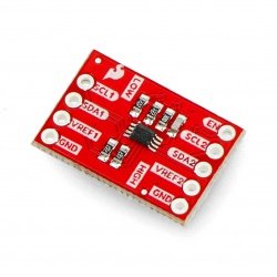
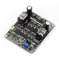
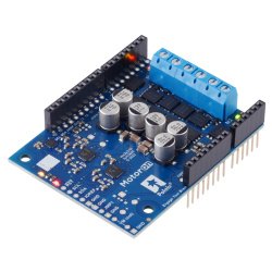
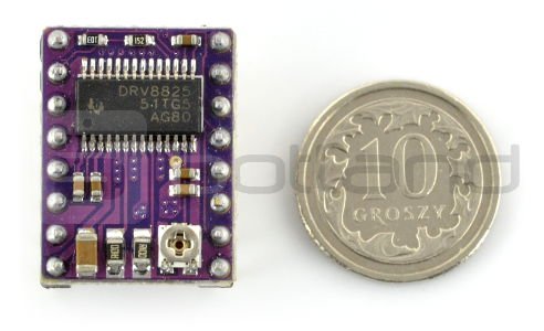
The module is based on the DRV8825 driver from the Texas Instruments, it allows you to control a stepper motor with maximum current consumption of up to 1.5 A per coil (withthe use of cooling, up to 2.5 A). It is supplied with the voltage ranging from 12 V to 24 V. Before the use, it is recommended to see thedocumentationof the driver DRV8825.
Key features
- The module has a simple interface of step and direction control.
- It has the possibility of operating in six modes: full-step, half-step, 1/4-step, 1/8-step, 1/16-step, and 1/32-step.
- It provides control of maximum motor current with the potentiometer, which allows the use of higher than rated voltage for motors.
- The engines can be powered with voltage from 12 V to 24 V.
- Current consumption is up to 2.5 A (1.5 A without external cooling).
- Thanks to the built-in voltage regulator, the user does not have to have an additional power supply of logical part.
- DRV8824 works with systems with a voltage of logic parts of 3.3 V and 5 V.
- The open fields of the weight from below, enables soldering the cooling elements.
- The module is compatible, when it comes to dimensions and leads, with the system based on the controllerA4988.
|
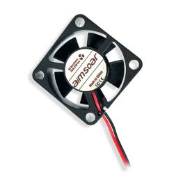
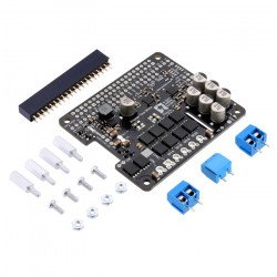
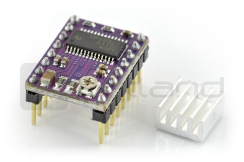
The set includes all the necessary elements to connect the driver - module with soldered goldpin connectors and the radiator for the self-assembly. |
Management
One pulse indicated on the STEP pin, causes one step of the motor in the direction selected by indicating the appropriate logic state (high or low) on theDIRlead.STEPandDIRpins are not internally pulled up. If the motor needs to rotate in only one direction, pinDIRcan be permanently connected toVCCorGND.
| Pin | Description |
|---|---|
| DIR | The choice of the direction of rotation by the low and high state. |
| STP | One pulse indicated on the STEP pin,causes one step of the motor. |
| SLP |
Sleep mode - activated by low state.
|
| RST |
The Reset is activated by the low state.
|
| M2 | Pin to select the resolution, details in the remaining part of the description. |
| M1 | Pin to select the resolution, details in the remaining part of the description. |
| M0 | Pin to select the resolution, details in the remaining part of the description. |
| EN |
Enable - indicating the low state means turning on the system.
|
| GND | The ground of the system. |
| FLT | Through the low state (logical zero), it indicates the emergence of disorders in the system's operation, for example, the activation of one of the securities. In order to keep the system compatible with the A4988, 5 V should be indicated on this pin. |
| 2A | Output for connecting the coil of the stepper motor. |
| 1A | Output for connection of the coil of the stepper motor. |
| 1B | Output for connection of the coil of the stepper motor. |
| 2B | Output for connection of the coil of the stepper motor. |
| GND | The ground of the system. |
| UMOT | Supply voltage of the motors from 12 V to 24 V. |
Power
The system can be powered with any voltage from 12 to 24V connected between the UMOT (+) and GND (-) pins.
|
Attention! In certain conditions, even a relatively low supply voltage may result in voltage peaks with a high amplitude, exceeding the allowed value of 24 V. This situation causes irreversible damage to the system. One way to avoid this problem is placing the capacitor (at least 47 uF) as close as possible to VMOT and GND pins of the module of controller.
The connection and disconnection of the engine while the driver is turned on, can damage the system. |
Resolution
Micro-step driver, like the DRV8825, allows engine operation with high resolution up to 1/32 of step. The step size is selected using inputs M0, M1 and M2 - the available modes are presented in the table below. By default, all three pins are pulled down to ground via resistor. Leaving them not connected means the choice of operation mode with full step. For example, when using a motor with a resolution of 200 steps per revolution, choice of the mode of ¼ of steps means working with a resolution of 800 positions per revolution.
| M0 | M1 | M2 | Resolution |
|---|---|---|---|
| Low | Low | Low | Full step |
| High | Low | Low | 1/2 of step |
| Low | High | Low | 1/4 of step |
| High | High | Low | 1/8 of step |
| Low | Low | High | 1/16 ofstep |
| High | Low | High | 1/32of step |
| Low | High | High | 1/32of step |
| High | High | High | 1/32of step |
Current limit
To maintain high switching speed of steps, you can use a higher motor supply voltage than rated. You should only limit the maximum current flowing through the coils up to the value of engine performance.
The module allows for the active current limit with the potentiometer. One of the ways of introducing the restriction, is setting the driver to full step mode and measuring the current flowing through one coil without indicating the signal on the STEPinput. The measured current is 70% of the set limit (both coils are always on and limited to 70% in full step mode).
Useful links |


