Connection of bipolar and unipolar stepper motors
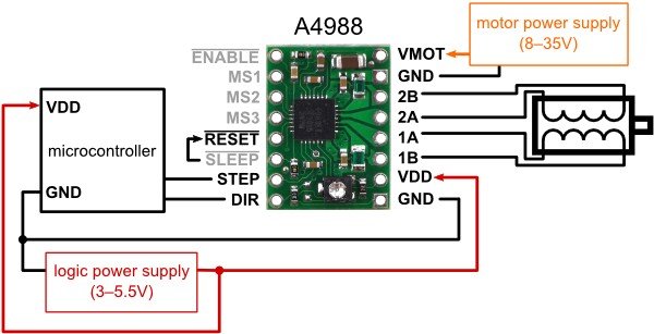
Both bipolar and unipolar motors can be controlled using the A4988 controller. Below is an instruction on how to connect the outputs:

Diagram of connection of stepper motor to A4988 controller.
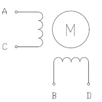
Four-wire bipolar motor connection

The figure shows the four-wire bipolar motor leads.
The outputs should be connected:
| Motor |
Controller A4988 |
Controller DRV8834 |
|---|---|---|
| A | 1A | A1 |
| C | 1B | A2 |
| B | 2A | B1 |
| D | 2B | B2 |
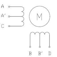
Six-wire unipolar motor connection

Six-wire unipolar motor outputs.
The wires should be connected as in a bipolar motor. Leave the A' and B' leads disconnected. They will not be used in bipolar control.
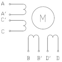
Connecting an eight-wire unipolar motor

Eight-wire unipolar motor outputs.
The motor has two coils per phase, the leads give direct access to each of them. For bipolar control, the coils can be connected in series or parallel. By choosing a parallel way we reduce the inductance of the coil. We recommend serial connection.
Parallel connection:
| Motor |
Controller A4988 |
Controller DRV8834 |
|---|---|---|
| A and C' | 1A | A1 |
| A' and C | 1B | A2 |
| B and D' | 2A | B1 |
| B' and D | 2B | B2 |
Serial connection:
- Output A' must be connected to C'
- Output B' to be connected to D'
- A C B' must be connected as in a bipolar motor


