Settings
- Supply voltage: 5 V
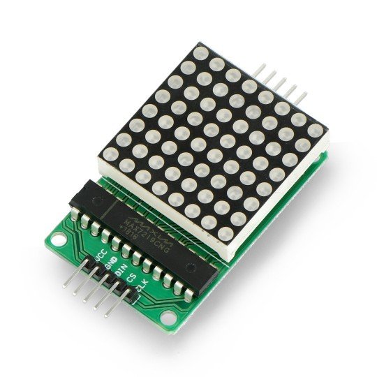
- LED matrix 8 x 8
- Communication interface: SPI
- Led color: red
- Module dimensions 50 x 32 mm
- Matrix dimensions: 32 x 32 mm
Included
- PCB
- LED matrix 8 x 8
- Driver MAX7219 with stand
- Electrolytic capacitor 10 uF / 25 V
- Ceramic capacitor 100 NF / 25 V
- Resistor 10 kOhm
- Set of goldpin connectors
|
Kit requires basic soldering of separate electronic components. |
Description
The set includes a display in a form of aLED matrix 8 x 8 with a controller and all necessary passive elements. The MAX7219 control system communicates via the SPI bus, which means it can be easily controlled using microcontrollers including AVR and Arduino modules. The description, together with a library and a sample program for usersof Arduinocan be foundhere.
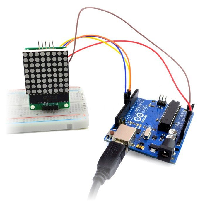
To start the module with Arduino using thelibrary, you must connect: DIN - PIN 12, CLK - PIN 11 CS - PIN 10.
Outputs are populargoldpin connectors(2.54 mm pitch) for connecting the sensor viawiresor directly to the breadboard.
Installation
Elements should be placed in marked on the PCB holes and solders. We recommend you to pay attention while mounting the electrolytic capacitor 10 uF, as it polarized. This means that the negative pole (-) should be soldered into the holes marked with the symbol -. In the properly soldered female connectors and in the stand you should place, respectively, the LEDmatrix and driver MAX7219.
Useful links |


