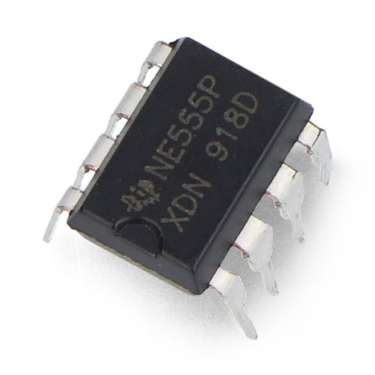
Product specification: Universal timer IC NE555 - THT
- Supply voltage: 4.5 to 16 Volts
- The maximum power dissipation of 600 MW
- Maximum output current 100 mA
- Current at 5 V supply: 3mA
- Current at supply voltage of 15V: 10mA
Details inthe documentation.
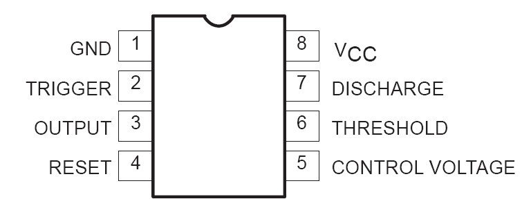
The pins of the NE555 IC:
1. GND- ground of the system
2. TRIGGER- trigger input. When a voltage lower than 1/3 of the supply voltage is applied to this input, the system is triggered and a high state appears at the output.
3. OUT- output of the system
4. RESET- specifying a low state resets the system. When the output is set to low, the external capacitor is discharged.
5. CONTROLarea is designed to change the proportions of the internal voltage divider.
6. THRESHOLD comparator input for disconnecting the internal flip-flop. When voltage higher than 2/3 of the supply voltage appears at this input, the system output will be set to low.
7. DISCHARGEoutput used to discharge an external capacitor. This is the output of the collector of the internal transistor.
8. VCC- power of the chip.
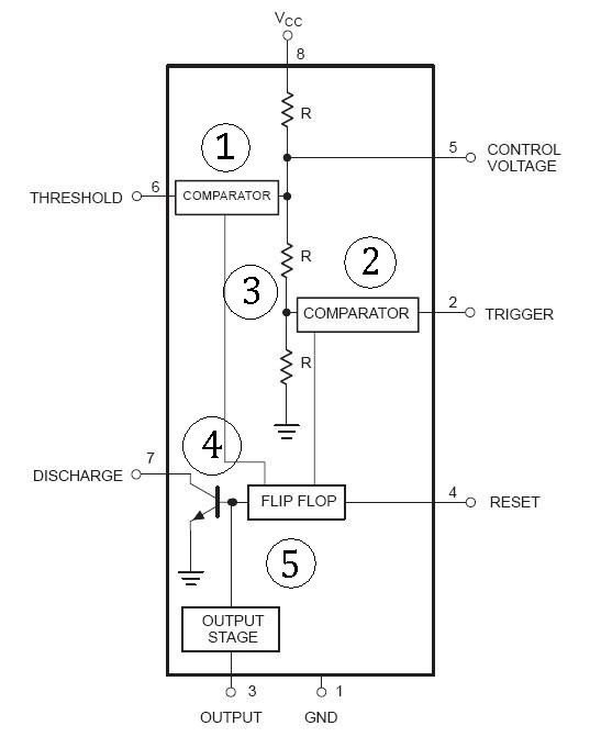
Diagram NE555
1.Comparator disabling the trigger
2.Comparator enabling the trigger
3.Resistor divide (R=5kOm)
4.Trigger
5.Discharging transistor.
Resistor divider sets the threshold voltage for comparators respectively 1/3 (1) 2/3 (2) of supply voltage.
In out range there is also an IC in SMD case, as well as a stand.


