Product description: LSM6DSO - 3-axis accelerometer and gyroscope I2C / I3C / SPI - Pololu 2798
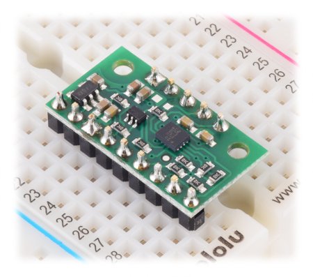
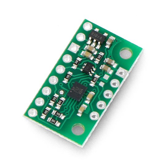
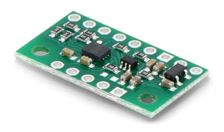
The LSMDDSO sensor from Pololu is the successor to the older LSM6DS33 module for measuring the acceleration field and angular velocity in three axes. It is characterized by small size, low energy consumption and simple operation. It uses the I2C/I3C or SPI bus for communication. The outputs are solder pads to which goldpin connectors (not included) can be soldered, enabling the sensor to be connected via wires or directly plugged into the breadboard . The module is equipped with a 3.3 V voltage regulator, thanks to which it is possible to work with a voltage of 1.8 V to 5.5 V. The regulator output is available on the VDD pin and can supply external circuits with a current of up to 150 mA.
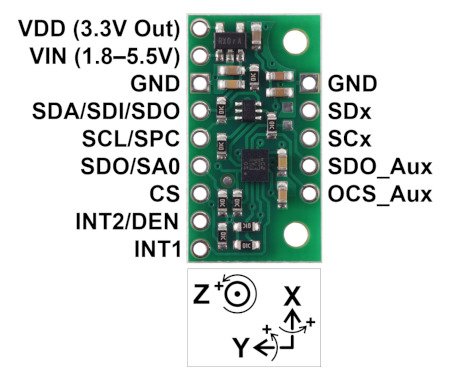
Pins of the LSM6DSO sensor
The sensor has 13 leads in the form of solder pads for mountinggoldpin connectors - raster 2.54 mm (not included) or connection cables. The SCL and SDA pins tolerate a voltage above 3.3 V because they are connected to a voltage converter. The remaining pins are not connected to it and do not tolerate 5 V, so they should be connected through an external logic level converter.
| Name | Description |
|---|---|
| VDD | Regulated output 3.3 V, maximum 150 mA. |
| VIN | System power supply from 1.8 V to 5.5 V. The converter aligns the SCL and SDA pins for the I2C and SPI buses to this level. |
| GND | System weight. |
| SDA / SDI / SDO | Data line for I2C / I3C and data input line for SPI. High is equal to VIN, low is 0V. |
| SCL/SPC | Clock line for I2C/I3C and SPI. High is equal to VIN, low is 0V. |
| SDO / SA0 | Data output line for SPI. High state is equal to VDD, low state is 0 V. It works with a voltage of 3.3 V. |
| CS | Data bus selection. High state (VDD) enables I2C communication (set by default). Low state enables the SPI bus. |
| INT2 / DEN | Programmable interrupt. Works with a voltage of 3.3 V. Details in the documentation . |
| INT1 | Programmable interrupt. Works with a voltage of 3.3 V. Details in the documentation . |
| SDx | Mode 2: I2C master data line (MSDA). Mode 3/4: auxiliary SPI data line (SDI). This pin is not connected to the voltage regulator. |
| SCx | Mode 2: I2C master clock line (MSCL). Mode 3/4: Auxiliary SPI clock line (SCK). This pin is not connected to the voltage regulator. |
| SDO_Aux | Mode 3/4: 4-wire SPI auxiliary line. This pin is not connected to the voltage regulator. |
| OCS_Aux | Mode 3/4: Activation of 4-line auxiliary SPI. This pin is not connected to the voltage regulator. |
Specification LSM6DSO
- Supply voltage: 1.8 V to 5.5 V
- Current consumption: 1mA
- Three axes: X, Y, Z
- Communication interface: I2C, I3C, SPI
- Measuring ranges (configurable):
- Accelerometer: ±2, ±4, ±8, ±16g
- Gyroscope: ±125, ±250, ±500, ±1000, ±2000 °/s
- Size: 23x12.7x2.5mm
- Weight: 0.6 g (without connectors)

Module with soldered connectors (not included).


