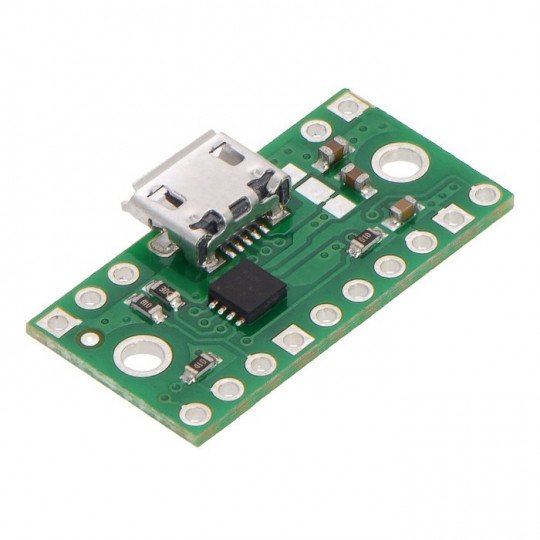
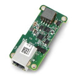
Product description: microUSB power connector with TPS2113A multiplexer
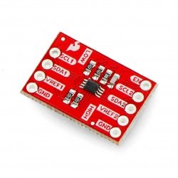
The module allows for selection of the power source from the two connected input lines. Power supply ranges from 2.8 V to 5.5 V, should be connected to the microUSB connector or goldpin terminal IN1 and IN2. The output voltage obtained from the goldpin output is marked OUT.
The multiplexer has an adjustable limitation of the maximum current and also the possibility of setting the voltage threshold which, if exceeded, the power supply switches. By default works in auto mode, which means that the source with the higher voltage is selected. Inputs can also be switched manually, details are in the remaining part of the description.
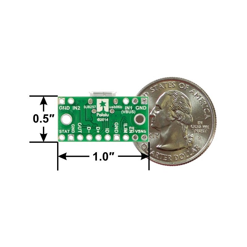
The board gives access to the inputs through traditional goldpin connectors - raster 2.54 mm. Due to this, the module can be mounted directly on the breadboard or to a plug with wires. Board sizes 25.4 x 14,0 x 3,8 mm.
In our offer we also multiplexer USB FPF1320 that is a smaller board and works with lower voltages and has lower energy efficiency.
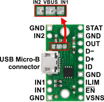
Inputs of microUSB power connector
| PIN | Description |
| IN1 | The input of the power bus 1. Allows you to connect voltage in therange from 2.8 V to 5.5 V. By default connected to the power line of microUSB connector via the jumper on the board. The input IN1 can operate with a supply voltage of 1.5 V, while input IN2 in specified voltage above 2.8 V. |
| VINB | The input of the power bus 2. Allows you to connect voltage in the range of 2.8 V to 5.5 V. |
| VBUS | 5 V voltage from the microUSB connector. By default, connected to the power bus 1 (IN1) through the jumper on the board. |
| OUT | Output voltage. |
| GND | The ground of the system. All pins marked with this symbol are connected (also with the ground of the microUSB connector). |
| VSENS |
Input power supply:
The PCB has a pull-up resistor to the ground, which sets the system to automatic switching mode. Detail in the remaining part of the description. |
| EN |
The input connected with the low statewill disable the output OUT. The board has a 100 kω pull-up resistor, making the default layout turned on. |
| ILIM |
Input for limiting the maximum current. Using built-in pull-up resistor the default limit is set to 0,5 A. To change the limit you need to solder an additional resistor, detail in the remaining part of the description. |
| STAT |
The status output. STAT is in low state when you select source IN1, goes to high when the selected source is IN2 (pulled up through a resistor of 100 ohms). |
| D− D+ ID |
Output USB interface:
|
Module support
The input voltage should lead to the outputs of bus 2 (IN2) and 1 (IN1), which are connected to the microUSB connector. Pin VSENS determines the mode of operation of the device. The default output in the low state, which means that the system operates in auto mode. Higher voltage is targeted on the source output. If the voltage on pin VSENS exceeds the value of 0.8 V, it will output the voltage of the source IN1, regardless of its value.
The module provides the ability to set a threshold voltage, beyond which the source switches. For this you need to solder an additional resistor between the VSENS and bus IN1, which will create a voltage divider with pull-up resistor to the mass of 20 ohms. The threshold voltage is determined by the following formula:

- R - soldered additional resistor.
This formula is valid until the voltage drops below 0.8 V, below this value, the module switches to auto - select the source with higher voltage.
The EN pin allows the VOUT output to be completely disconnected. Giving a low state to this output causes that there will be no voltage at the output. Regardless of what will be connected to bus A and B. On the board there is a pull-up resistor (100 kΩ), which makes the system switched on by default.
Pin ILIM adjusts the maximum current that can be provided by the multiplexer. The default layout was set to 0.5 A via a 1kω resistor. You can change the value by soldering additional resistor between the output and GND ILM. Current limit is defined by the following formula:

- R - soldered additional resistor.
To get the maximum current limit - 2A, you should solder the resistor 330 Ohms.
Connect the power connector microUSB
The module can be used by connecting the power to the inputs of type goldpin raster 2.54 mm (in the set for self soldering) or via the microUSB cable.
-
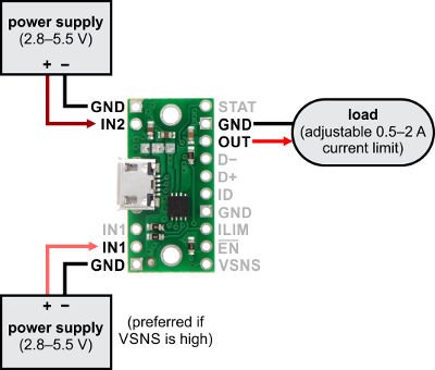
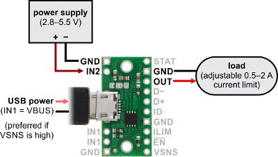
Connection without USB cable
When connecting, as shown above, the output will be transferred to the source with higher voltage. If the VSENS pin is in the high state, the preferred source is IN1.
-
USB cable as a primary source
If the pin VSENS is in a high state, the default source is IN1. Low state as VSENS causes to switch to the auto mode. To pass IN2 onto the output by default, it is necessary to cut the jumper between IN2 and VBUS and solder a new on ebetween VBUS and IN2 (figure below).
Useful links |
