Description
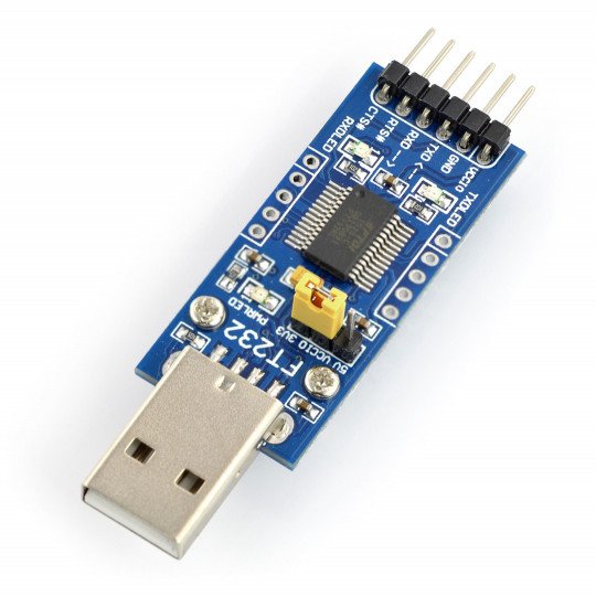
The converter allowsconnectionbetween two popular serial interfaces USB and UART. The module is based on aFT232RL and works with Windows 7 and WIndows 8/8.1.
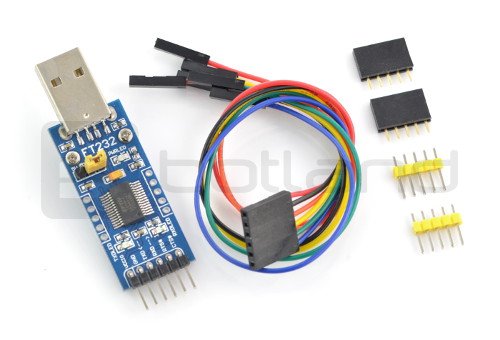
To the module is attached the6-pin cable with the female ends and the necessary pins.
The module can be used to exchange data between the computer and the microcontroller system or to program the boards with output serial interface e.g.ArduinoorSTM32Discovery. In the operating system, it is visible as a virtual COM port. It has 3 LEDs indicating the power, sending and receiving data.
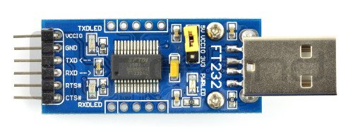
The device works with voltages of 3.3 V and 5 V. The voltage selection is done using jumper. Board has connectors with pitch 2.54 mm suitable for breadboard or to connect using wires. Pins VCCIO, GND, TXD, RXD, RTS# and CTS# have already solderedgoldpin connectors - 2.54 mm pitch. The rest are sold separately and to self-soldering.
Connection
The description of the leads of the chip are in the table.
| Pin | Description |
|---|---|
| VCCIO | Power 3.3 V or 5 V selected by jumper |
| GND | The mass of the system. |
| TXD | The pin of UART transmitter. |
| RXD | The pinof the receiver UART. |
| RTS# |
The control signal of request of data transmission / handshake signal. |
| CTS# | The control signal of transfer, details inthe documentation. |
| RESET# | The reset signal is activated with low state. |
| DCD# | Ambulance signal, the details inthe documentation. |
| DSR# | The ready datasignal, the information in thedocumentation. |
| RI# | The input of the controlindicator, the details inthe documentation. |
| DTR# |
The control signal of the ready data / handshake signal. |
| CBUS0 - 4 | Configurable pins CBUS, the details inthe documentation. |
Useful links |


