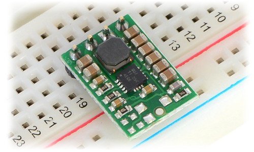
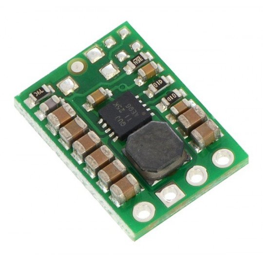
Product description: S7V8F5 - step-up/step-down converter - 5V 1A.
The S7V8F3 is a buck-boost pulse voltage regulator that converts 2.7V - 11.8V input voltage to 5V output with an average efficiency of 80%. The input voltage can be lower, higher or equal to the input value, which makes the system functional and universal. The flexibility of the input voltages makes the system ideal for battery-powered systems where stability of the supply voltage and its independence from the battery charge level is required.
Examples of application
- Maintaining a stable voltage of 5V in systems powered from a basket with four NiMh batteries (sticks), which when fully charged give a voltage of about 6, partially discharged below 5V.
- Power supply of the systems with 5V from a single Li-Po cell during the entire battery discharge cycle.
- Power supply of 5V systems from a 9V battery, which partially discharged may give a voltage below the required one.

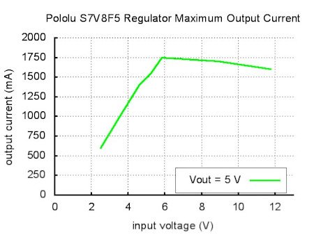
In standard application, the system allows for current draw up to 1A in step-down mode, i.e. when the supply voltage is higher than the desired output voltage. When the input voltage is lower than the output voltage (step-up mode), the current capacity of the inverter decreases as shown in the diagram below.
The graph shows the dependence of the maximum current capacity on the input voltage.
Use
The module has four outputs: VIN input voltage, VOUT output voltage, GND ground and SHDN pin which switches the system into standby mode.
- VIN- input voltage from 2.7 V to 11.8 V. At lower voltage the controller will not start. Higher one may permanently damage the system.
- GND- ground potential.
- VOUT- 5 V output voltage
- SHDN- low state (below 0.4 V) switches the system to low power consumption. The current consumption in the sleep mode depends on the resistor (100 kΩ) pulling SHDN to VIN and is 10 uA per volt. For example, when the VIN supply voltage is 5 V, the system will draw 50 uA.
The connectors are properly signed on the board.The output roaster is 2.54 mm (popular goldpin connectors). The module can be plugged into acontactboard,connected with wiresor soldered intoa dedicated PCB.
Inverter efficiency
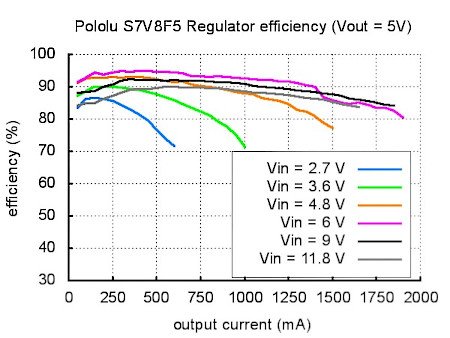
Efficiency isdefinedas the ratio of input power to output power (Pout/Pin). This parameter is particularly important for battery operation when it is important to keep the system running as long as possible on a single charge. The efficiency of the inverter depends on the flowing current and the input voltage (graph below). On average, it is at the level of 80-95%, which allows to use practically maximum energy from the battery.
Efficiency of the controller for 5V output voltage.
Voltage jumps (pins)
In electronic circuits the starting current may cause the occurrence of so-called pins, i.e. sudden voltage surges to a value above a set level. If the amplitude of the pins exceeds the permissible value of the regulator, it can be destroyed. Therefore, if the circuit will be supplied with voltage above 9V or the load will have high inductance, we recommend solder a capacitor of 33uF or higher as close to the circuit as possible between VIN and GND.
Polol S7V8F5 inverter specifications
- Input voltage: 2.7V to 11.8V
- Maximum output current:
- 1 A (step-down)
- 0.5 A (step-up)
- Output voltage: 5 V
- Temperature protection
- Short circuit protection
- Dimensions: 11.5 x 16.5 x 2.54 mm
- Weight: 0.6 g (without connectors)
Useful links |


