Description
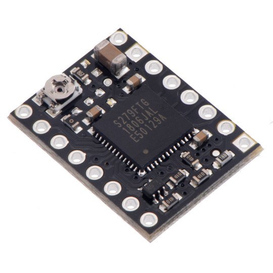
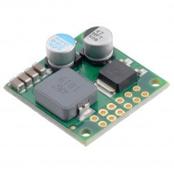
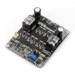
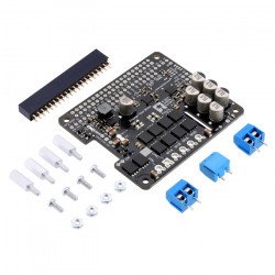
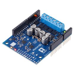
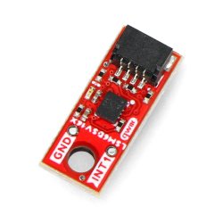
The system allows to control the stepper motor by means of a device allowing to generate logical states e.g.Arduino,STM32Discovoery,Raspberry Piany folkmicrocontrollerThe Polol module is very simple to use. The increasing slope of each pulse on the CLK (STEP) output corresponds to one step.The selection of the direction is made by specifying the appropriate state on the CW/CCW (DIR) output (e.g. low state - clockwise rotation, high state - counterclockwise).The controller also has a choice ofmotorresolution.
|
The module has no goldpin connectors soldered in. We also offer a version with solderedconnectors. |
Controller connection
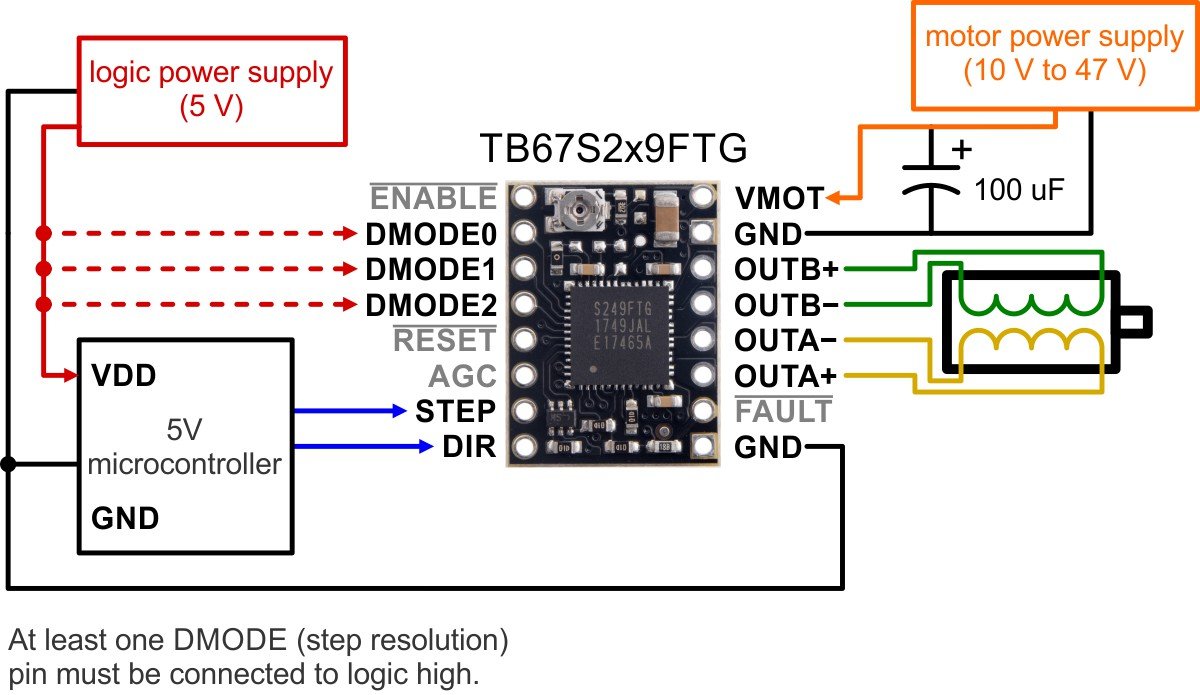
To control the bipolar stepper motor, connect the system as shown in the figure below.
Minimum wiring diagram to connect the microcontroller to TB67S2x9FTG.
The controller requires supply voltage from 10 V to 47 V which will be connected to VIN and GND outputs.
Power supply
A voltage of 5 V is required to supply the logical part of the module, which must be led to the pinVDD. The motor supply voltage from 10 V to 47 V is given per pinVIN.
|
Attention! Connecting and disconnecting the motor while the controller is on can damage the system. |
Resolution
Step size is selected using inputs DMODE0, DMODE1, DMODE2. The possible settings are shown in the table below. Inputs MS1, MS2 and MS3 have an internal pull-down resistor (100kΩ).
| MS1 | MS2 | MS3 | Resolution |
| low | low | low | Standby mode |
| low | low | high | Full step |
| low | high | low | non-wheeled half step ("a") |
| low | high | high | 1/4 step |
| high | low | low | circular half step ("b") |
| high | low | high | 1/8th step |
| high | high | low | step 1/16 |
| high | high | high | 1/32 step |
Control
The increasing slope of each pulse on the CLK (STEP) output corresponds to one step. The direction is selected by entering the appropriate state on the CW/CCW (DIR) output (e.g. low state - clockwise, high state - counterclockwise). If the motor is to turn in one direction only, the DIR pin can be left unfastened.
When the RESET pin goes into high state, the controller resets its state in the translator array, which leads to the initial value of 45°. This corresponds to 100% of the current limit on both coils in full steps and non-wheeled half stage modes. Pin RESET does not switch off the motor outputs, the controller will continue to supply current to the motor but will not give information to the CLK output.
The TB67S2x9FTG can detect several error states they report, causing one or both LO contacts to be low. The manufacturer has included inthe documentation a table of error combinations on LO1 and LO2 pins.
A detailed description of each pin can be found onthe manufacturer's website.
Useful links |
