Description
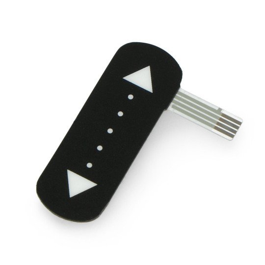
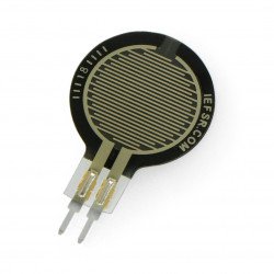
The pressure sensor changes its resistance depending on the size and point of application of force on the measurement bar with the length of 36 mm. To run the sensor, needed is a resistor from the range of 4.7 kΩ to 10 kΩ which is not included in the set but can be purchased separately. Sensor along with a display, makes it easy to create a touch interface of any device.
The film shows an example of a device that uses a linear potentiometer as an advanced switch for LED lighting.
Specification
- External dimensions: 38 x 13.5 x 0.7 mm
- Dimensions of the measured area: 36 x 10 mm
- Weight: 0.5 g
- The self-adhesive layeron the bottom for facilitating the mounting
- Pins' pitch of the tape: 1 mm
More details in the documentation.
|
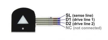
The findings of the sensor are ended with the tape with copper pads with the pitch of 1 mm. At the present time, we do not have the appropriate connectors but the ribbon works with FFS sockets, pitch of 1 mm. |
Connection
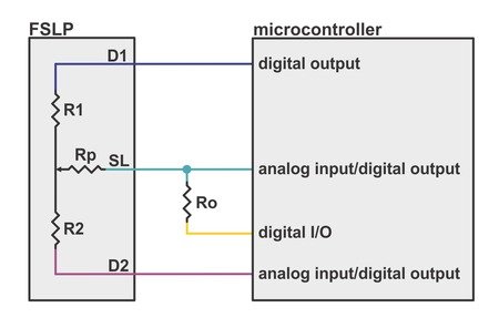
The sensor has three pins - at the tape are four pads but the last is not in use. For reading data, it is necessary to apply an external resistor with the value in the range of 4.7 kΩ to 10 kΩ. The sensor requires four lines of the microcontroller, including two that are able to read the analog value - the input of the A/D converter. The connection example is shown in the diagram below.
Measurement of the force of pressure
The resistance Rp depends directly on the pressure force, it changes in the range from 300 kΩ (for light touch) to approximately 1 kΩ (for the strong pressure).
If the D1 pin will be entered to the high status, and the lower R0 connection to the low status, then the SL line will be the output generated from the resistors R0 and Rp of the voltage divider. The measurement on the line D2 will give the value of the input voltage of this divider. Having the value of SL line and the line D2, it is easy to compute the value of the resistance Rp which is directly connected with the pressure force.
The optimal value of the resistor R0 depends on the specific project, however, the manufacturer recommends that it should be selected from the range of 4.7 kΩ to 10 kΩ.
When the pressure doesn't work on the measuring strap, the Rp resistance reaches several MΩ. In practice, it means that the voltage on the line R0 will be close to zero (it is determined by connected to ground, the resistor R0). It can be used for digital detection of the absence of pressure on sensor.
The position measurement
The sensor can also be used as a linear potentiometer - switch is in the form of a touch slider. If applied to the sensor, point will move, the value of one of resistors (R1 or R2) will decrease, and the second increase. In the case of movement in the opposite direction, the situation with the resistors will reverse.
If the D1 pin will be entered to the high status, connection D2 to a low status, the SL line will be the output of the voltage divider created from the R1 and R2 resistors. At this time, the lower connection of the resistor R0, must be set as input (high impedance status). Measuring the voltage at SL line, we get the value of the voltage proportional to the position of the applied force. The value of this voltage is in the range from 0 V (the potential of the ground) to VCC (supply voltage).
When the pressure doesn't work on the measuring bar, the SL is practically connected to nothing and does not provide the significant measurements. This fact can be used for digital detection of the absence of the pressure on the sensor (see the paragraph above).
|
This sensor has the outputs with high impedance. It can hinder the accurate measurements of the voltage using the analog-to-digital converters mounted in microcontrollers. The complete measurement procedure, along with helpful information on how to reduce the effect of interference and improve the accuracy, can be found in the user guide. |
Useful links |
