Description
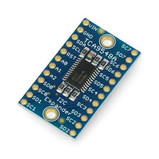
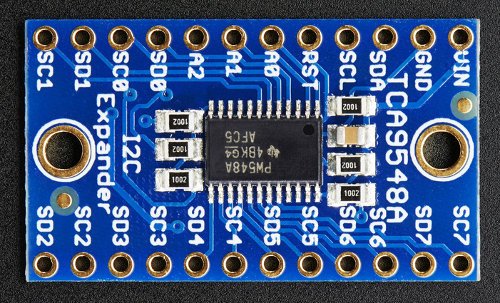
Module with a multiplexer TCA9548A allows you to connect 8 different digital I2C interface to one interface, for each there are separate pins SDx (x busdata line) and SCx (x bus clockline). Working voltage from 3 V to 5 V, the address of the output I2C bus can be changed.
| The product is compatible with Arduino
The manufacturer has prepared auser guide that contains the detailed description of the device and an example of connecting to Arduino. |
Connection
Outputs are solder fields for soldering goldpin connectors(2.54 mm raster - included in the set). Thanks to them, it is possible to connect the system with thebreakout boardor the main module (e.g.Arduino) usingwires.
| Pin | Description |
|---|---|
| VIN | Supply voltage from 3 V to 5 V. |
| GND | The ground of the system. |
| SCL | Clock line of output / I2C bus. |
| SDA | Data line of output / I2C bus. |
| RST | The reset is activated by low state. By default pulled up to the voltage VIN through the resistor. |
|
A0 A1 A2 |
Output for changing the address of the main I2C bus. By default pulled up to ground make up the 0x70address. By setting to high state you can change the address range from 0x71 to 0x77. |
| SCx | Line delayed-action input / quests / multiplexed tothe I2C bus. |
| SDx | Line input / quests / multiplexed to the I2C bus. |
Specification
- Supply voltage: 3 V to 5 V
- Multiplexer: TCA9548A (documentation)
- Connection input: I2C bus
- The possibility of changing the address of input I2C bus from 0x70 to 0x77
- Switchable 8 separate I2C
- Outputs: goldpin connectors 2.54 mm raster (included for self-soldering)
- Board sizes: 31 x 18 x 3 mm
- Weight: approx. 2 g
Details in the technical documentation.
Useful links |


