Product description: Cytron Maker Line - strip with reflective sensors
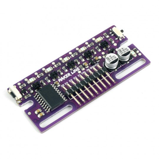
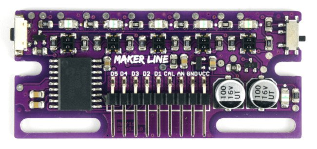
The Cytron module equipped with5 reflective sensors (pair: IR diode and phototransistor) is able to track 13 to 30 mm wide lines in white and black. The sensor has2 types of signal outputs, digital, for each of the 5 sensors separate and one common for the analog signal, thanks to this solution the sensor is compatible with a wide range of controllers such as Arduino or Raspberry. The module operates with a voltage of3.3 and 5 V. Additionally, the module is protected against reverse polarity.
The board is equipped with 5 reflective sensors (pair: IR diode and phototransistor).
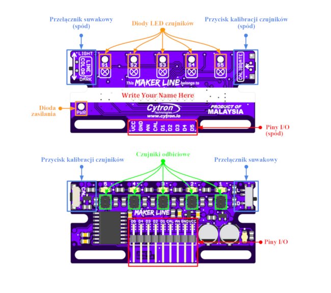
Elements on the board Cytron Maker Line - line tracking sensor
Cytron Maker Line supports 2 types of outputs. Digital outputs in the form of 5 separate pins for each sensor, which after detecting an object go into high state and an analogue output whose output voltage represents the position of the line. Analogue output offers higher resolution compared to digital outputs.
| Outputs | Description |
|---|---|
| Slide switch | It is responsible for the selection of the color with which the sensor is to work. Choose between white or black. |
| Sensor LEDs | The LEDs light up when the selected color is detected. |
|
Sensor calibration button |
The button allows you to calibrate the sensor. This is necessary for the sensor to be able to distinguish between the ground and the line being traced. |
|
Power LED |
LED that indicates power supply to the sensor. |
|
I/O pins |
Input/output pins on the board
|
|
Reflective sensors |
Reflective sensors for line detection. |
Calibration of Cytron Maker Line sensor - line tracking sensor
calibration of the sensor is required to be able to distinguish the ground from the line it is supposed to follow. To perform the calibration, press the button for 2 seconds, drag the sensor along the line and then press the calibration button again. The calibration data is stored in the sensor's EEPROM so that it does not have to be performed every time the device is switched on. Calibration should be performed again if the sensor height, line colour or background colour changes.
Video showing sensor calibrations.
Sensor Measurement Cytron Maker Line - Reflective sensor strip
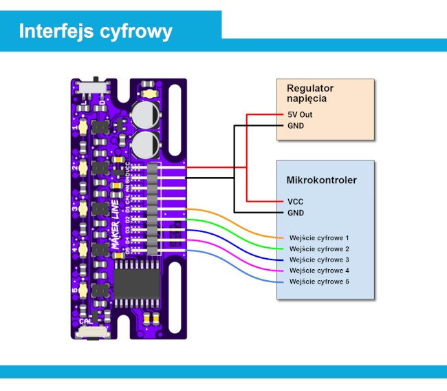
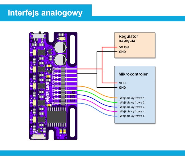
The following are the output values with the connection diagram for both communication interfaces. Detailed information about this can be found in thedocumentation preparedby the manufacturer.
-
Digital interface
| Slide switch | Sensor | LED(Sx)* | Digital output |
|---|---|---|---|
| Light | Bright surface | Ongoing | High state |
| Light | Dark surface | Excluded | Low state |
|
Dark |
Bright surface | Excluded | Low state |
| Dark | Dark surface | Ongoing | High state |
-
Analogue interface
| Line position | No line | Left | Measure | Law | An overrun was detected |
| Analogue output |
Less than 0.1 x VCC |
0.1 x VCC | VCC / 2 | 0.9 x VCC |
More than 0.9 x VCC |
| Analogue output (VCC=3.3V) |
0 to 0,33 V | 0,33 V | 1,65 V | 2,97 V | 2,97 to 3,3 V |
|
Analogue output |
0 to 0.5 V | 0,5 V | 2,5 V | 4,5 V | 4.5 to 5 V |
Specification Cytron Maker Line - Reflective sensor strips
- Power supply voltage: 3.3 V and 5 V
- Digital outputs: D1 to D5
- Low state: 0 to 0.5 V
- High state: 0.7 V to VCC
- Analogue output:
- 0 V to VCC
- Detection distance:
- from 4 to 40 mm
- Frequency of refreshment: 200 Hz
- The width of the detected line:
- 13 to 30 mm
- Dimensions: 68 x 28 x 7 mm
- Weight: 14 g
Useful links |
