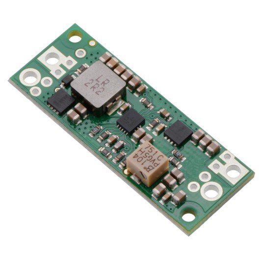
Product description: step-up inverter U3V70A - adjustable - from 4.5 V to 20 V 10 A.
A controller that increases theinputvoltagefrom2.9 V to 20 Vto an output value selected by a potentiometerfrom 4.5 V to 20 V, assuming that theoutput voltage cannot be lower than the input voltage.The system is able to process a maximum input current of10 A, a typical input current brings8 A for a few seconds, after which thethermal protectionmode is activated. It is recommended to useup to 6 A, the inverter can then runfor many minutes. The output current is a function of the input voltage, output voltage and inverter efficiency. Details can be found in the diagrams below.
The U3V70x family offers one version of the inverter with adjustable output voltage:U3V70A (4.5 - 20 V). Constant voltage versions are also available:5 V,6 V,7.5 V,9 V,12 Vand15 V. All versions of the U3V70x are similar to each other, for ease of identification there is a blank space on the back where you can place your ownmarker.
Connecting the U3V70A inverter
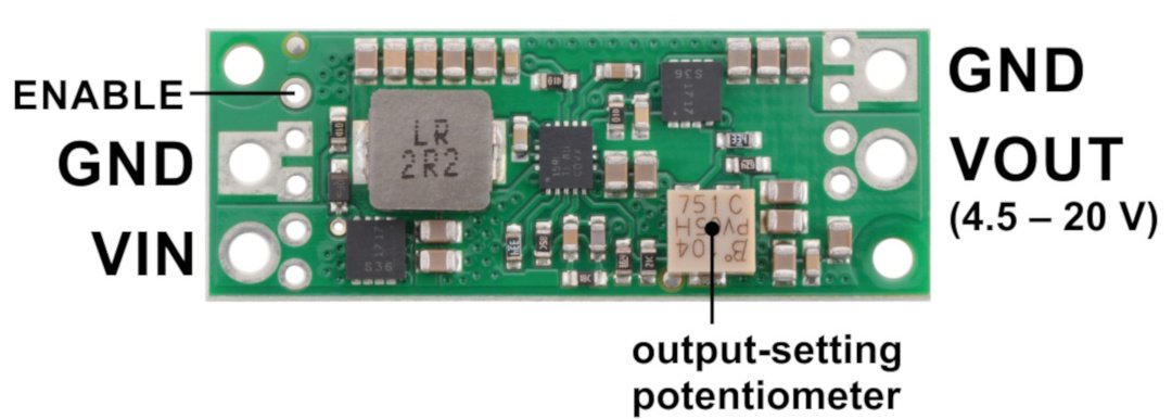
The module has four outputs:
- VIN- input voltage, must not exceed the output voltage.
- GND- ground potential.
- VOUT- output voltage. In case of adjustable version it is selected by means of a potentiometer.
- ENABLE- switches the system into low power consumption state. By default, the pin is pulled up to the VIN supply voltage via a 100 kΩ resistor. This means that if the output is left unconnected, the inverter is switched on by default. In order to put the circuit into standby mode, the low state (below 0.4 V) must be given. In this situation, the module only consumes current flowing through the 100 kΩ resistor, which is 10 µA depending on the input voltage being connected.
The connectors are properly signed on the board. The output roaster is 5 mm for ARK connectors and 2.54 mm for connectorsgoldpinwhich allow the module to be mounted incontact plateorconnectionby means ofcables.
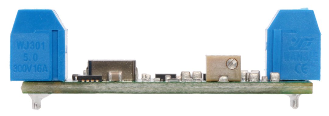
Soldering connectors for self-soldering are included. You can choose popular goldpins or ARK high-current terminals. Thanks to the thicker PCB layer the terminals do not stick out of the circuit.
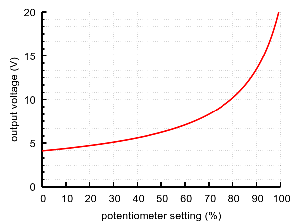
Output voltage selection for model U3V70A
The voltage is set using a 12-turn potentiometer. A multimeter can be used to select the appropriate value. Turning the potentiometer to the right increases the output voltage.
Fig.: Output voltage selection.
Output current and efficiency of step-up system U3V70A
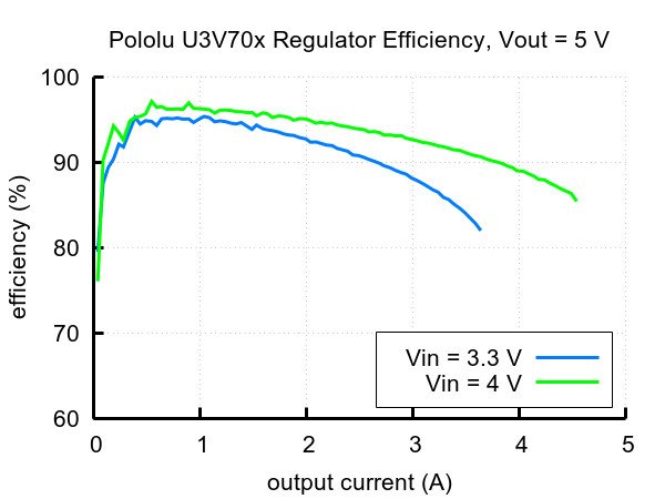
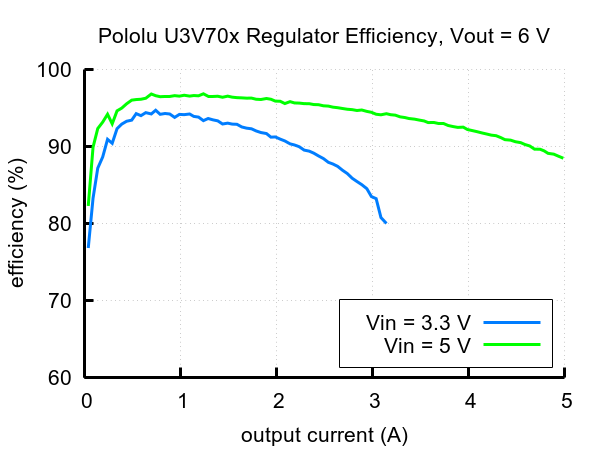
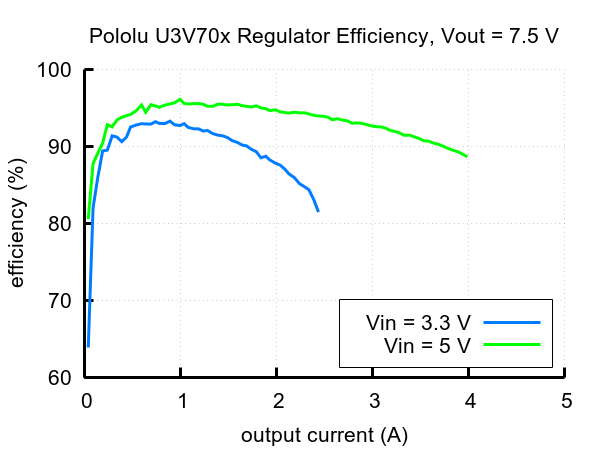
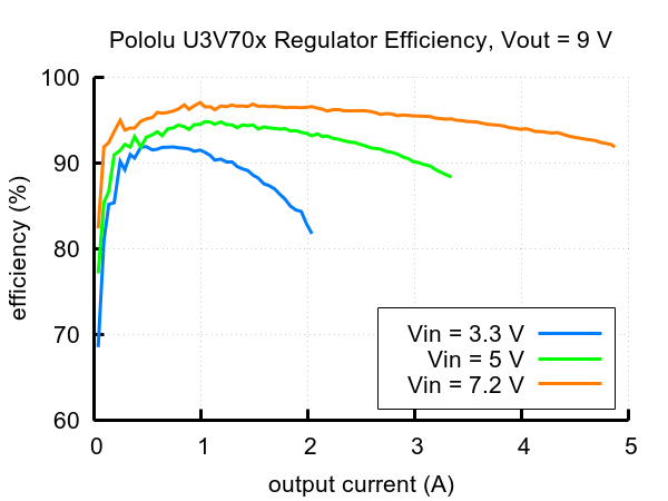
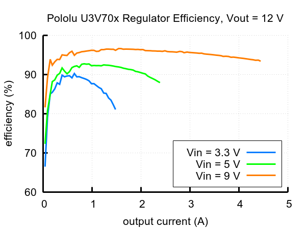
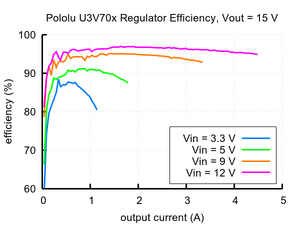
The efficiency of the inverter depends on the input voltage and the selected output voltage. On average, it ranges from 80 % to 95 %. The output current is a function of the input voltage, output voltage and inverter efficiency. It is usually the value around the input current.
Figure 1: System efficiency at 5V output voltage.
Figure 1: System efficiency at 6V output voltage.
Figure 1: System efficiency at 7.5V output voltage.
Fig. 1: Efficiency of the system at the output voltage of 9V.
Fig. 1: Efficiency of the system at the output voltage of 12V.
Fig. 1: Efficiency of the system at the output voltage of 15V.
To sum up, the maximum output current is proportional to the ratio of input voltage and output voltage. Additionally, its value may depend on external factors, e.g. temperature or air flow or the heatsink used.
Specifications of the U3V70A step-up converter
- Input voltage: 2.9 V to 20 V
- Output voltage: 4.5 V to 20 V - adjustable by potentiometer
- Maximum input current:
- up to 10 A - instantaneous
- to 8 A - for a few seconds
- up to 7 A - for an extended period
- Output current: see graphs
- Low power consumption at rest
- Efficiency of 80 - 95 %
- Security:
- Before reverse power connection
- Thermal - switches off the system at too high a temperature
- Switch-on interlock at too low a supply voltage - below 2.5 V
- Short circuit
- Input current limitation to 10 A
- Two mounting holes for M2 screws
- Dimensions: 40.6 x 15.2 x 4.6 mm
- Weight (without connectors): 3,4 g
Useful links |
