Description
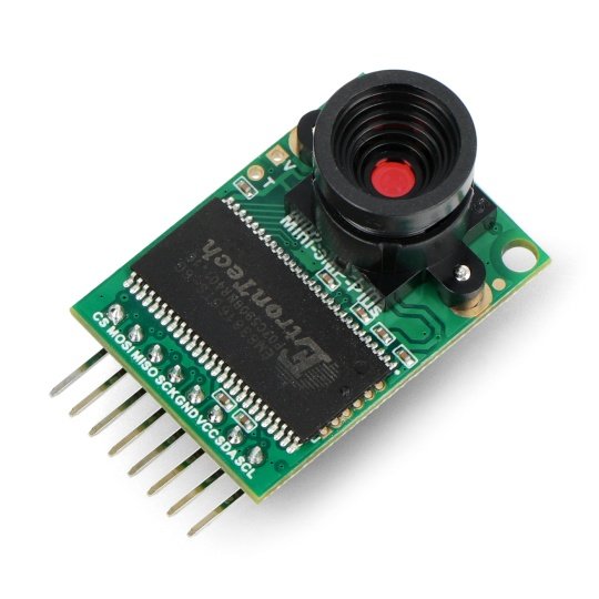
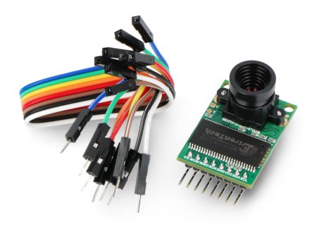
Camera module for Arduino 5 MPx with a resolution of 2592 px x 1944 and speeds up to 120 frames per second. It extends the capabilities of the system, for example, microcontrollers Arduino, STM32 and mini-computers Raspberry Pi, with the possibility of taking photos and recording video clips. The device operates with a voltage of 3.3 V and 5 V, it communicates via SPI, the angle of view - 24 ° (non-linear), the lens is 1/4".
Modes of operation
- Single Capture Mode - the default mode of the device after the indicating the command via SPI, the camera captures a frame and adds it to the buffer, while setting a flag in the registry. By checking the state of the flag, the user knows that the read has been completed.
- Multiple Capture Mode - an advanced mode where the user specifies the number of frames to be captured. Please note that the number of frames cannot exceed the capacity of the buffer.
- JPEG Compression - in this mode, the output are compressed data in the JPG format with higher resolution, than RGB.
- Normal Read and Burst Read Operation - in this mode, it is sufficient to send a read command for receiving the continuous transmission of frames via an SPI interface.
- Rewind the Read Operation - it allows to read, several times, the same data contained in the buffer.
- Low Power Mode - disables the sensor and transducer in order to save energy.
- Image Sensor Control - mode change parameters of the camera sensor, i.a. balance, brightness, contrast and saturation.
|
The product is compatible with Arduino A user manual and library for Arduino are available in GitHub. |
Block diagram
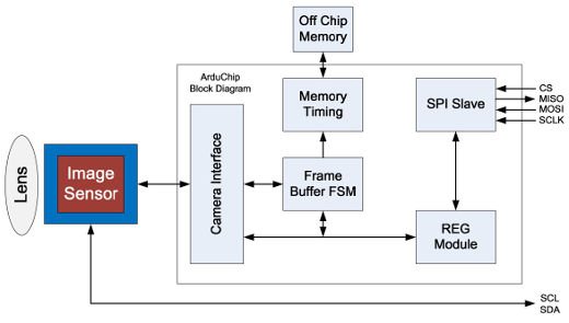
The device consists of a lens, sensor and electronic components with the data buffer and the controller of the SPI bus. The user has also access directly to the sensor via the I2C bus.
A block diagram of the camera module ArduCAM-Mini.
Specification
- Working voltage: 3.3 V / 5 V
- Maximum resolution: 2592 px x 1944 (5 MPx)
- The number of frames per second:
- up to 120 FRAMES per second for the format of QVGA (320x240px)
- up to 60 FRAMES per second for VGA 640x480px)
- up to 60 fps for 720p (1280c720px)
- up to 30 FRAMES per second for 1080p (1920x1080px)
- up to 15 FRAMES per second for 5 MPx (2592x1944px)
- Lens size: 1/4 "
- Lens mounting: CS-mount / M12
- Pixel size: 1.4 µm x 1.4
- Range of image: 3673,6 x 2738,4 µm
- Angle of view: 24 ° (non-linear)
- Output formats:
- 422/420 YUV / YCbCr 422
- RGB565/555/444, CCIR656
- compressed 8-bit data
- 8 / 10-bit RAW RGB Data
- Configuration of sensor through I2C bus
- Module dimensions: 35 × 25 mm
The details in the technical documentation of the sensor OV5642.
Pins
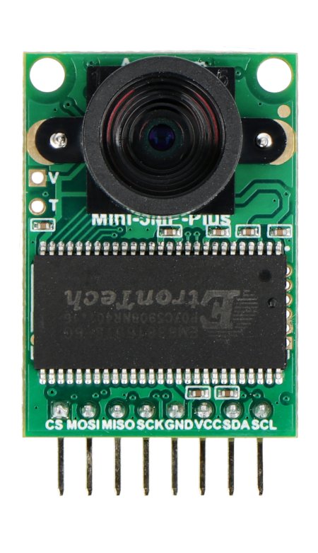
The device has soldered the 8 pin connector, pitch of 2.54 mm.
| Pin | Name | Description |
|---|---|---|
| 1 | CS | Chip Select - selects a device on the SPI bus, activated by low state. |
| 2 | MOSI | Data output line of SPI bus. |
| 3 | MISO | Data output line of SPI bus. |
| 4 | SCK | Clock line of the SPI bus. |
| 5 | GND | The ground of the system. |
| 6 | VCC | Supply voltage from 3.3 V to 5 V |
| 7 | SDA | Data output line of I2C bus. |
| 8 | SCL | Clock line of the I2C bus. |
Useful links |


