- Sale
- SPECIAL OFFERS
Specification
- Supply voltage: 1.8 V - 3.6 V
- Consumption of the current: up ot 320 uA
- Three axes: X, Y, Z
- Measuring range: ± 3 g
- Communications: the analog signal - voltage
- Installed filters in the form of condensers of 100 NF for each axis
- Pins: holes forgoldpin connectors- 2.54 mm pitch
- The dimensions of the board: 18 x 18 mm
Description
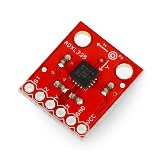
The module with ADXL335 accelerometer to measure accelerations in the three axes: X, Y, Z; in the range of +/- 3 g. The sensor is powered with the voltage in the range from 1.8 to 3.6 V. It consumes only 320 uA of current. The output is an analog voltage signal proportional to the measured acceleration. The sensor can be controlled using any microcontroller with analog-to-digital converter, for example, a set ofArduinoorSTM32Discovery.
|
The product is compatible with Arduino On the websitebildr.org, you can find a description of the connection with the sample program for Arduino |
Pins
The sensor has six pins for mounting the goldpin strap - 2.54 mm pitch (not included in package, sold separately). After soldering the connectors, the module can be connected usingwiresor attach it to the breadboard.
| Name |
Description |
| VDD | The module's supply voltage is in the range of 1.8 V to 3.6 V |
| GND | The ground of the system. |
| ST | Self Test - a detailed description inthe documentation. |
| X | Analog, voltage output signal of the X axis with the value proportional to the measured acceleration. |
| Y | Analog, voltage output signal of the Y axis with the valueproportional to the measured acceleration. |
| Z | Analog, voltage output signal of the Z axis with a value proportional to the measured acceleration. |
Useful links |


