


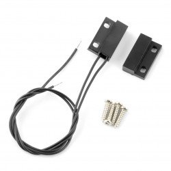


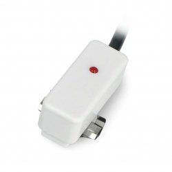


Arduino and the sensor end of the door opening
Quick start guide presented how to connect the Arduino and the sensor limit.
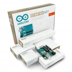
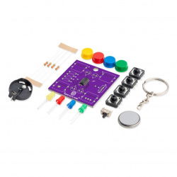
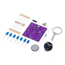
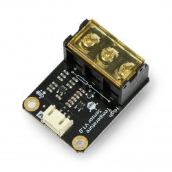
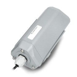
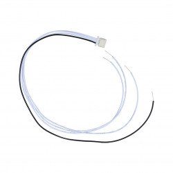
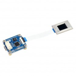
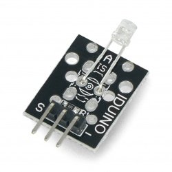
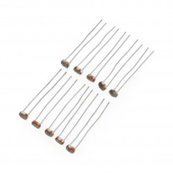
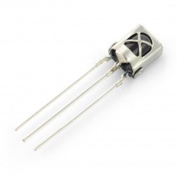
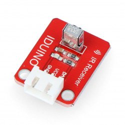
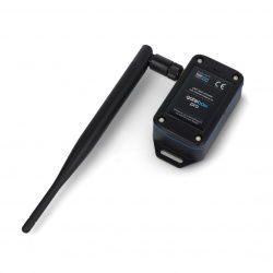
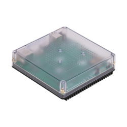
In this example we used the following elements:
Connect the sensor with Arduino:
The sensor using the Arduino you should connect the layout as follows:
| Sensor | Pin Arduino |
|---|---|
| The first contact sensor | 5 V |
| The second contact sensor | 2 |
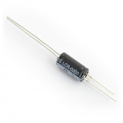
In addition, you should pull the line 2 to ground through a resistor such as 10 ohms, to keep a low as in the case of open doors, as well as in the following figure:
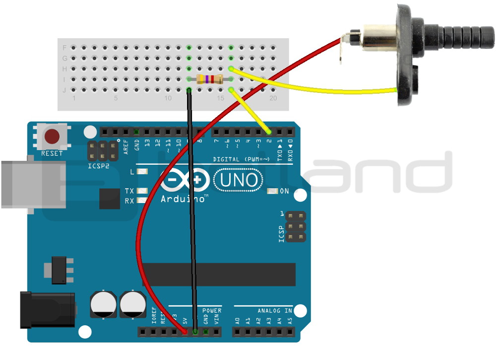
The connection scheme of sensor with the Arduino Uno.
Program for Arduino
The sensor is in a normal condition closes the loop. Pressing the button causes an open circuit (low pine 2). In the example, we used the following code:
int sensor = 2; //pin 2 is connected to the sensor

void setup() {
 Serial.begin(9600); //initialize serial monitor
 pinMode(sensor, INPUT); //setting Arduino pin as an input
 pinMode(13, OUTPUT); //pin 13 as output

 Serial.println ("---- TEST of SENSOR KRANCOWEGO ----");
}

void loop() {
 int war = digitalRead(sensor); //read the value from the sensor
 delay(1);
 //delay to eliminate vibration contact
 if (war == LOW) //display information on the serial monitor { //status low means that the bolt is clamped, condition, high - free bolt
 Serial.println(" Open doors");
 digitalWrite(13, HIGH); //also, in case of detection of the open door indicator from under the pin 13 lights up
 }

 else {
 Serial.println("Closed");
 digitalWrite(13, LOW); }
 delay(200); //delay between consecutive readings
}
The program displays messages on the display consistent. In addition, when detecting the door is open, the indicator under-pin 13 lights up. The effects of the program can be seen in the following screenshot:
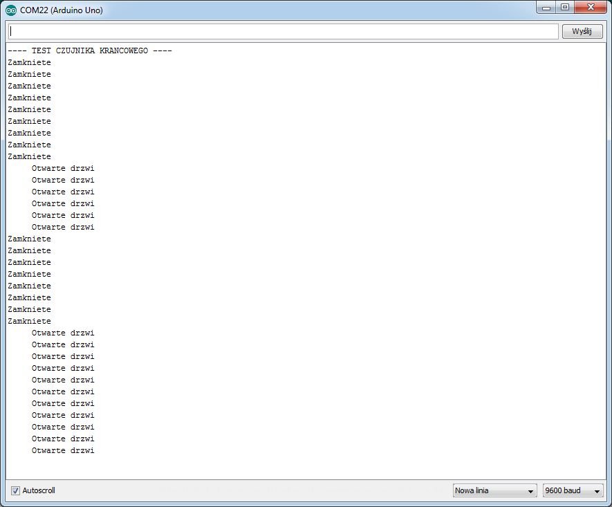
A screenshot of the serial monitor.