


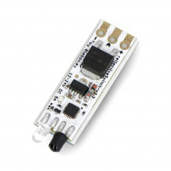

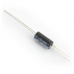


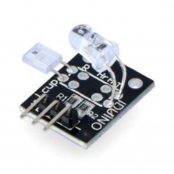

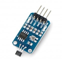


Phototransistor and Arduino
This guide shows how to use the phototransistor via Arduino.
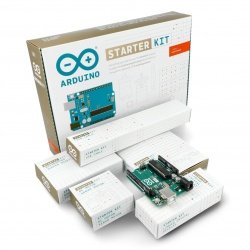
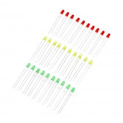
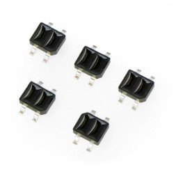
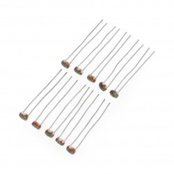
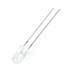
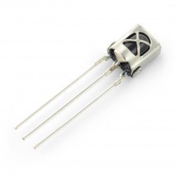
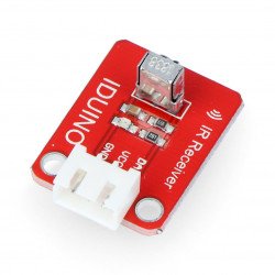
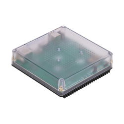
The following elements are used in the example:
Connecting the module with Arduino:
The circuit must be connected as follows:
| Phototransistor | Pin Arduino |
|---|---|
| Longer leg | A1 |
| Shorter foot | 5 V |
Additionally, the longer leg is pulled up to the ground by a 1 kΩ resistor (the resistor value can be selected experimentally). The connected circuit is shown in the diagram below:
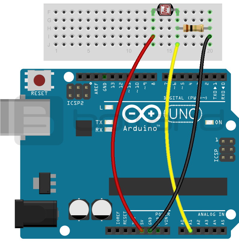
The diagram of connecting phototransistor with Arduino Uno.
Program to Arduino
The value from the phototransistor is read on the Arduino analog input. After exceeding a predetermined threshold the program lights up the diode from pin 13. Additionally, it displays the read value on the serial monitor all the time. In the example the following code was used:
int sensor = A1; //pin analogue A1 combined with a longer phototransistor leg

void setup() {
  Serial.begin(9600); //initialisation of a serial monitor
  Serial.println("Phototransistor test");
  pinMode(13, OUTPUT); //pin 13 set as output - diode
}

void loop() {
  int war = analogueRead; // reading the value from A1
  Serial.print(war); // display it on a monitor
  if (war > 400)
  {
    Serial.print(" LED lit"); // when the value exceeds a certain threshold, then the LED on pin 13 will light up
    digitalWrite(13, HIGH);
  }
  else
  {
    digitalWrite(13, LOW);
  }
  Serial.println("");
  delay(200); // Delay between readings
}
The effects of the programme can be observed on the following screen:
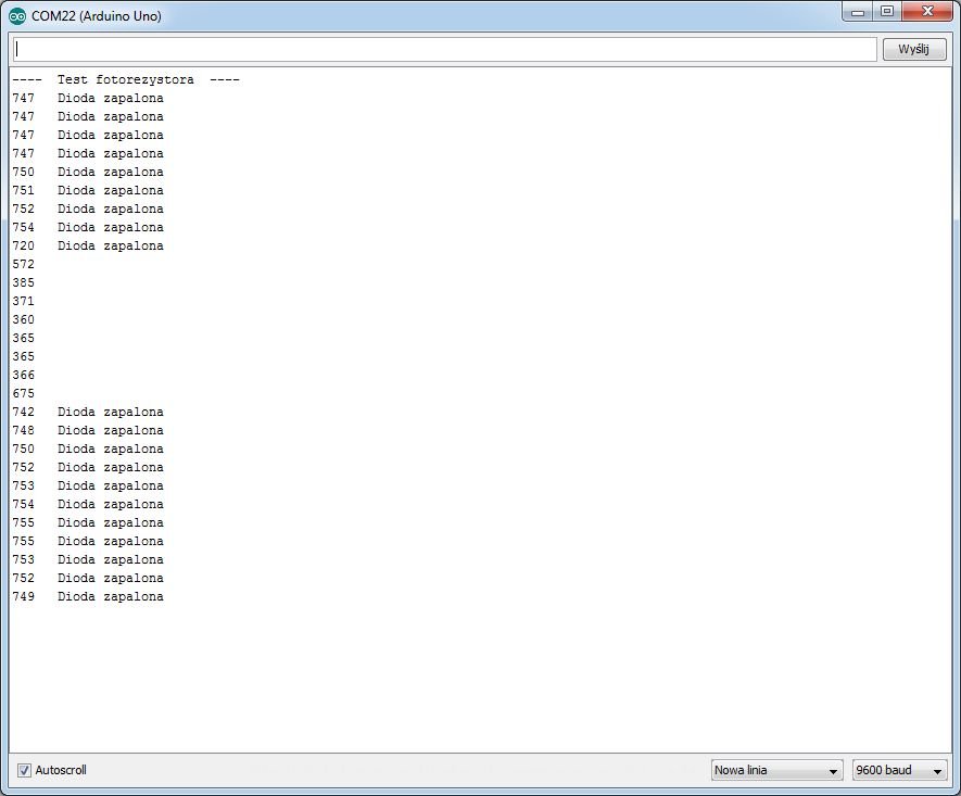
Serial screenshot of the monitor.