


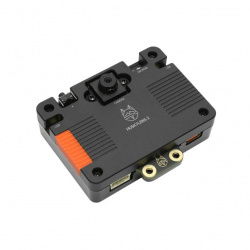


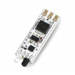


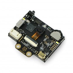


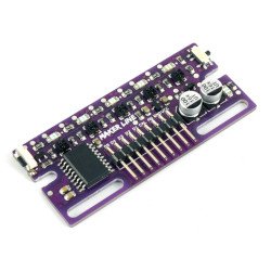


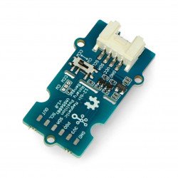


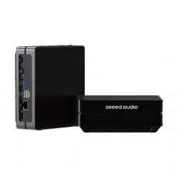


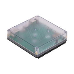


 The analog-to-digital converter (ADC) is a popular accessory for Raspberry Pi.Many cheaper microcontrollers now have a built-in converter, so this 8-channel converter is based on the STM32F030, which is an economical, energy-efficient ARM Cortex M0 microcontroller.The board has 8 ADC channels and 4 integrated analogue Grove connectors, so you can use it also with analogue Grove modules.
|
Buy now |
Properties
- CRC Calculation Unit
- 5-channel DMA controller (direct memory access)
- RTC Calendar with alarm and periodic wake up Stop / Standby
- Timers
- Timer with advanced control
- General timers and basic timers
- Independent time and watchdog timer
- SysTick timer
- Real Time Clock (RTC)
- Serial cable debugging (SWD)
Specifications
| Feature | Value |
|---|---|
| Operating voltage | 3.3 V |
| ADC resolution | 12 bit |
|
Maximum frequency clock |
48 MHz |
| Read memory size | 16 kB |
| RAM size | 4 kB |
| Data bus width | 32 bit |
| Working temperature | from -40°C to 85℃ |
| Communication interface | I2C |
| I2C address | 0x04 (default) |
| Dimensions | 65 x 55 x 18 mm |
| Weight | 25.9 g |
| Packaging dimensions | 140 x 75 x 25 mm |
| Gross weight | 45 g |
Typical applications
- Temperature measurement
- Consumer goods
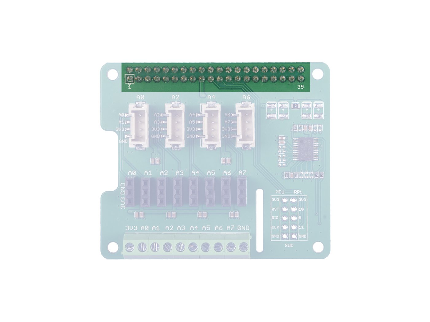
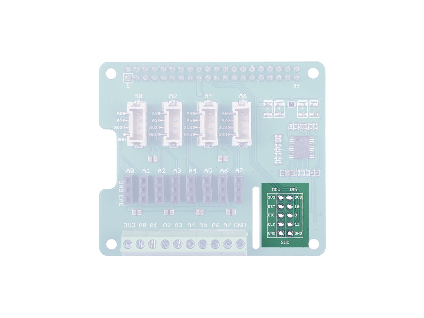
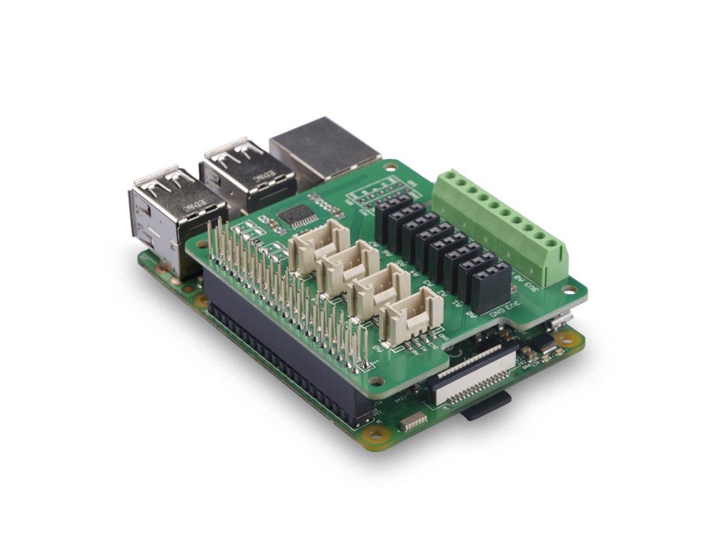
Equipment overview
Exit timetable
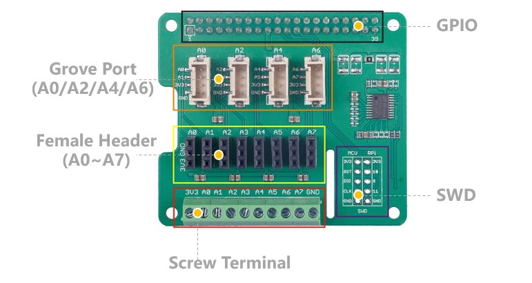 GPIO
GPIO
Same distribution as Raspberry Pi.
SWD
We use the SWD port to record the firmware on this board. Additionally in this section you can see pin 9 / pin 10 / pin 11. These three pins are not used by any Grove port, you can use them without worrying about pinning.
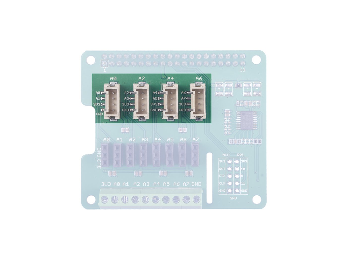
Grove Analog Port
As you know, there is no ADC on the Raspberry Pi, so this STM32-based ADC board allows the operation of analog sensors from the Raspberry Pi.
There are 4 analog Grove sockets on the board, so you can connect Grove modules directly with Grove -5 cm 4 pins Universal Band Cable.
The Analogue Sensor introduces analog voltage to the 12-bit ADC. After converting the analog data to digital, the sensor enters the Raspberry Pi via the I2C interface.
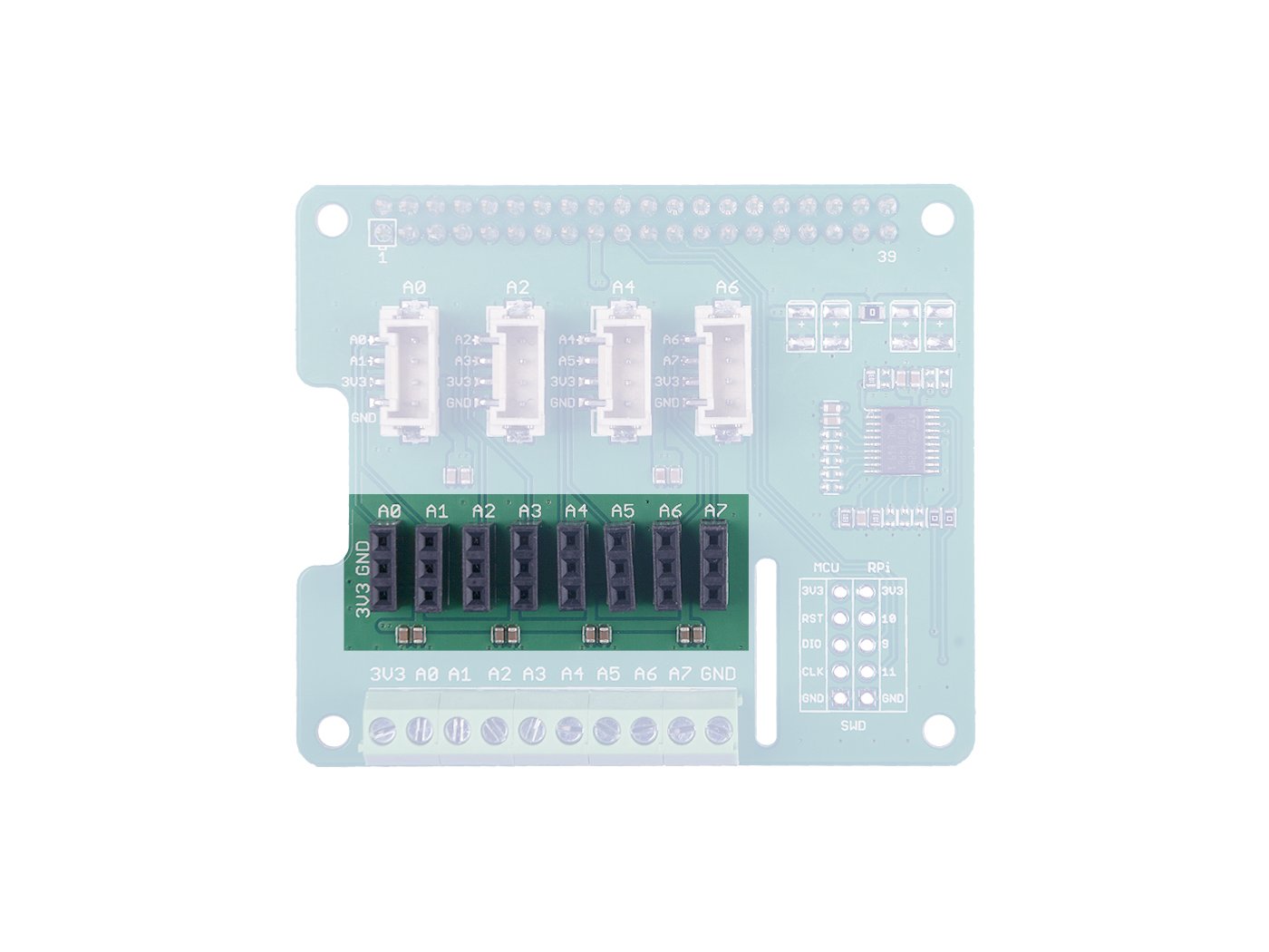
 Female pin connectors
Works similarly to Grove analogue ports, only instead of Grove -5 cm 4-pin Universal Strip Cableuse a set of wiresBreadboard Jumper Wire Pack.
8 analog connection ports, A0 ~ A7.
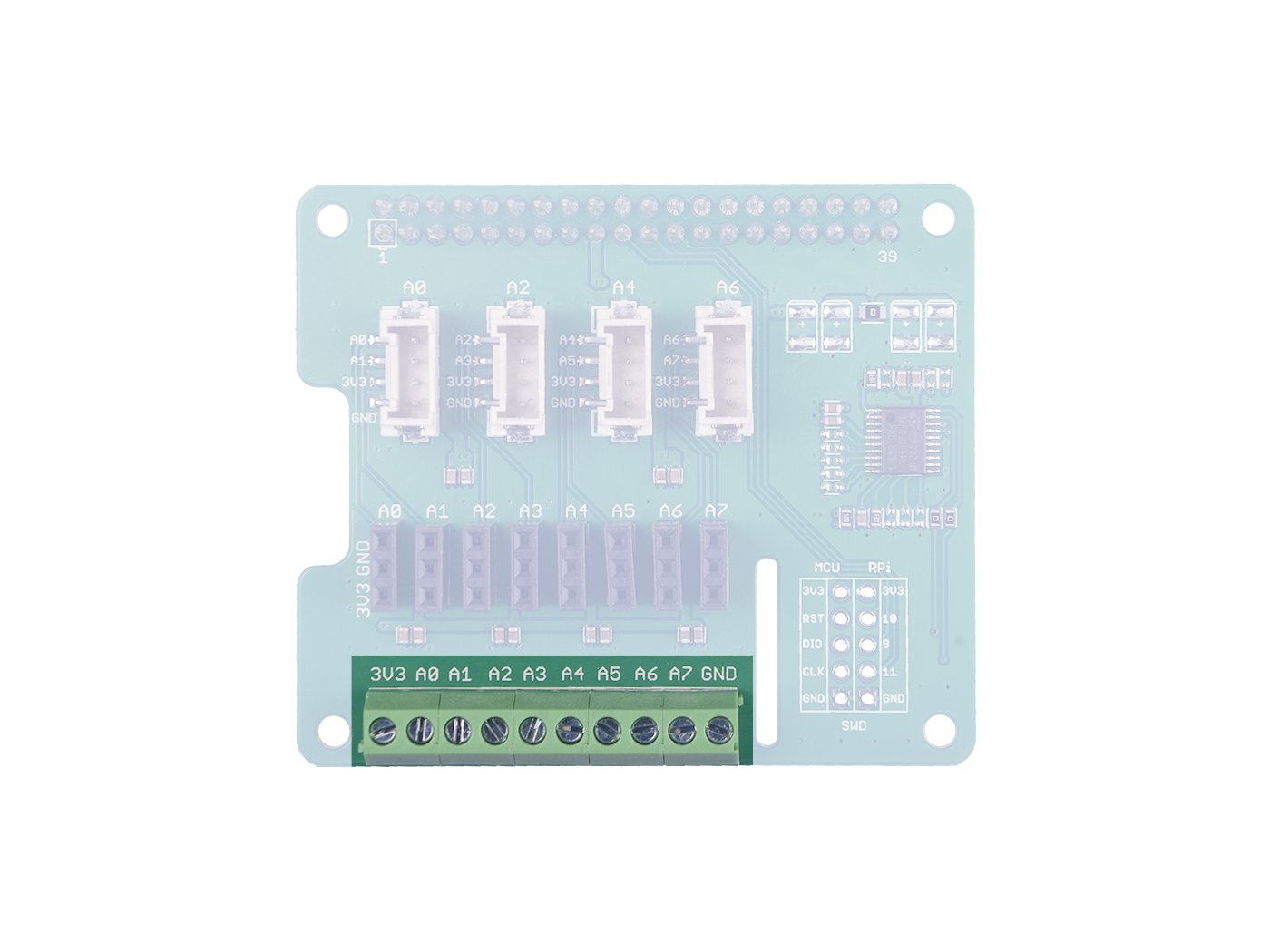
 Screw connections
Similar to the above, they only have a different connection method. This group contains analog pins A0 ~ A7, Vcc and GND.
How to start?
Hardware
Required materials
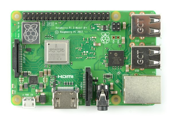
| Raspberry Pi |
8-channel 12-bit analogue-to-digital converter for Raspberry Pi(STM32F030) |
|---|---|
 |
|
- Step 1: Insert the transmitter intoRaspberry Pi.
- Step 2. Connect the Raspberry Pi to your computer via USB cable.
Software
- Step 1: Download the source file by cloning the grove.py library.
cd ~
git clone https://github.com/Seeed-Studio/grove.py
- Step 2. Install the grove.py library
cd grove.py
# Python2
sudo pip install .
# Python3
sudo pip3 install .
- Step 3 Follow these commands to execute the code.
cd grove.py/grove
python adc_8chan_12bit.py
Below is the code adc_8chan_12bit.py.
import time
from grove.i2c bus import

ADC_DEFAULT_IIC_ADDR = 0X04

ADC_CHAN_NUM = 8

REG_RAW_DATA_START = 0X10
REG_VOL_START = 0X20
REG_RTO_START = 0X30

REG_SET_ADDR = 0XC0


class Pi_hat_adc():
    def __init__(self,bus_num=1,addr=ADC_DEFAULT_IIC_ADDR):
        self.bus=Bus(bus_num)
        self.addr=addr


    #get all raw adc data,THe max value is 4095,cause it is 12 Bit ADC
    def get_all_adc_raw_data(self):
        array = []
        for and in range (ADC_CHAN_NUM):
            data=self.bus.read_i2c_block_data(self.addr,REG_RAW_DATA_START+i,2)
            val=data[1]<<8|data[0]
            array.append(val)
        return array

    def get_nchan_adc_raw_data(self,n):
        data=self.bus.read_i2c_block_data(self.addr,REG_RAW_DATA_START+n,2)
        val =data[1]<<8|data[0]
        return val
    #get all data with unit mv.
    def get_all_vol_milli_data(self):
        array = []
        for and in range (ADC_CHAN_NUM):
            data=self.bus.read_i2c_block_data(self.addr,REG_VOL_START+i,2)
            val=data[1]<<8|data[0]
            array.append(val)
        return array

    def get_nchan_vol_milli_data(self,n):
        data=self.bus.read_i2c_block_data(self.addr,REG_VOL_START+n,2)
        val =data[1]<<8|data[0]
        return val

    #get all data ratio,unit is 0.1%
    def get_all_ratio_0_1_data(self):
        array = []
        for and in range (ADC_CHAN_NUM): data=self.bus.read_i2c_block_data(self.addr,REG_RTO_START+i,2)
            val=data[1]<<8|data[0]
            array.append(val)
        return array

    def get_nchan_ratio_0_1_data(self,n):
        data=self.bus.read_i2c_block_data(self.addr,REG_RTO_START+n,2)
        val =data[1]<<8|data[0]
        return val


ADC = Pi_hat_adc()
def main():
    raw_data=ADC.get_all_adc_raw_data()
    vol_data=ADC.get_all_vol_milli_data()
    ratio_data=ADC.get_all_ratio_0_1_data()
    print("raw data for each channel:(1-8chan)(12 bit-max=4096):")
    print(raw_data)
    print("voltage for each channel:(unit:mv,max=3300mv):")
    print(vol_data)
    print ("ratio for each channel(unit 0.1%,max=100.0%):")
    print(ratio_data)

    print(" ")
    print("NOTICE!!!:")
    print("The default setting of ADC PIN is floating_input.")
    print(" ")

if __name__ === '__main__':
    main()
|
Success If you have done everything successfully, the following message should appear. |
pi@raspberrypi:~/grove.py/grove $ python adc_8chan_12bit.py
raw data for each channel:(1-8chan)(12 bit-max=4096):
[2177, 2098, 2064, 2038, 2127, 2066, 2172, 2145]
voltage for each channel:(unit:mv,max=3300mv):
[1599, 1741, 1668, 1658, 1644, 1787, 1694, 1677]
ratio for each channel(unit 0.1%,max=100.0%):
[521, 544, 514, 504, 500, 559, 524, 505]

NOTICE!
The default setting of ADC PIN is floating_input.
Example
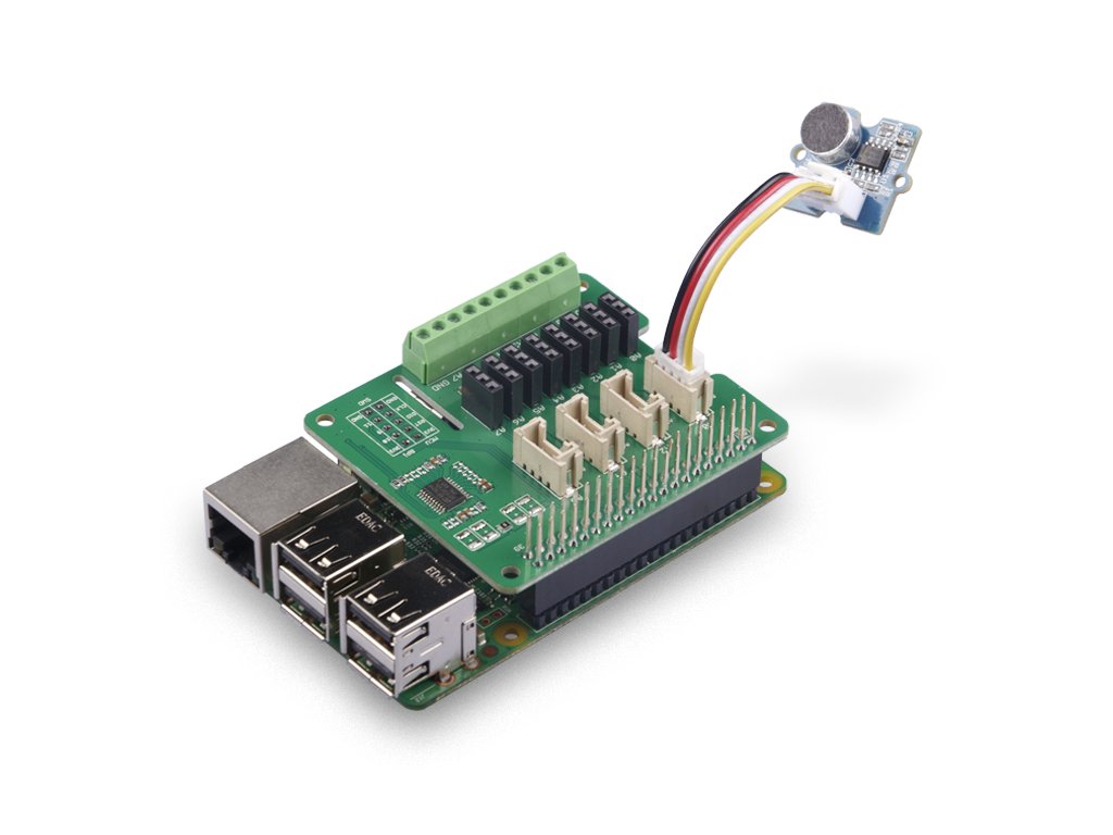
Let's takeGrove - Sound Sensoras an example to show how to use this tile.
Connecting equipment
- Step 1: Connect the transmitter to Raspberry Pi.
- Step 2 Connect the Grove - Sound Sensor via port A0 to the transmitter.
- Step 3. Connect the Raspberry Pi to your computer via USB cable.
Hardware wiring diagram
 Type the following command: ++python grove_sound_sensor.py 0++ in the command line.
pi@raspberrypi:~/grove.py/grove $ python grove_sound_sensor.py 6 Detecting sound... Sound value: 433 Sound value: 342 Sound value: 443 Sound value: 300 Sound value: 632 Sound value: 258 Sound value: 591 Sound value: 267 Sound value: 871 ^CTraceback (most recent call last): File "grove_sound_sensor.py", line 67, inmain() File "grove_sound_sensor.py", line 64, in main time.sleep(.3) KeyboardInterrupt
You can leave the program by pressingCtrl+C.
Links
-
[Zip] 8-channel12-Bit Raspberry Pi transmitter (STM32F030) Eagle files
-
[Zip] 8-channel12-Bit Raspberry Pi Transducer (STM32F030) Software library
-
[PDF]Technical DataSheetSTM32F030