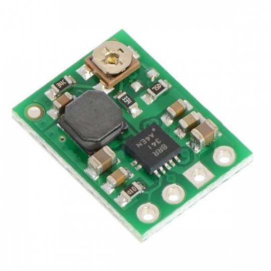
Product description: U1V11A - step-up converter - 2-5V 1,2A - Polol 2560.
A controller that increases the voltage from 0.5 to 5.5 V to apotentiometer-controlledvalue from 2 V to 5.25 V. When 5.25 V is exceeded at the input, the system automatically switches to rope-reducing regulator mode. The efficiency of the inverter is 70 - 90 %, depending on the specified input voltage. The system has a standby mode, which is switched on by giving a low state to the SHDN output. We also offer a version with an output voltage of 5 Vand3.3 V.
Outputs
The module has three outputs:
- VIN- input voltage from 0.5 V to 5.5 V, please pay attention toshort voltage pulses that can damage the system
- GND- mass potential
- VOUT-adjustable output voltage
- SHDN -system shutdown - low state, which makes the system go into low power consumption state. The output is pulled to the VIN via a 100 kΩ resistor, which makes the system switched on by default. If the pin is not used, it can be left unconnected or connected to an adjacent VIN. Otherwise, follow the instructions below:
- For VIN < 0.8 V, the voltage value at SHDN must be below 0.1 * VIN to lock the controller and above 0.9 * VIN to unlock it.
- For 0.8 V ≤ VIN ≤ 1.5 V, the voltage value at SHDN must be below 0.2 * VIN to lock the controller and above 0.8 * VIN to unlock it.
- For VIN >11.5 V , the voltage value at SHDN must be below 0.4 V to lock the controller and above 1.2 V to unlock it.
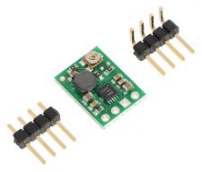
The connectors are properly signed on the board. Output Raster 2.54 mm - popular connectorsgoldpin, allow the module to be mounted incontact plateorconnectionby means ofcables.
Output voltage selection
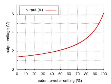
The voltage is set using a potentiometer. Turning clockwise increases the voltage.
Fig. 1: Selection of output voltage.
System efficiency
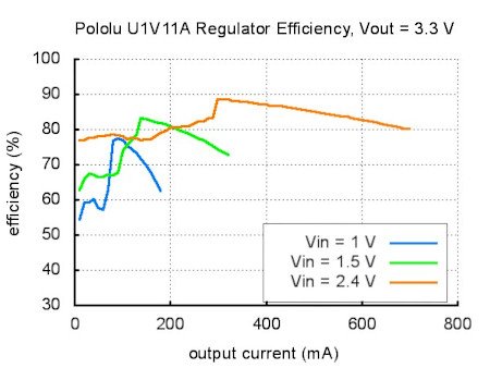
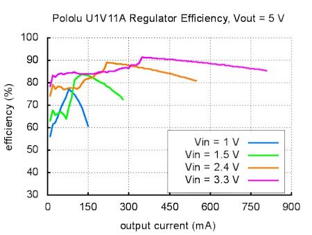
Efficiency is defined as the ratio of output power to input power (Power out)/(Power in). This is a very important parameter when working with portable energysources(batteries and accumulators), where the time of operation on one charging cycle counts. The efficiency of this pulse system is about 70 % - 90 %. The output current depends on the input voltage, details on the diagram:
Efficiency of the system at an output voltage of 3,3 V.
Efficiency of the system at an output voltage of 5 V.
Dangerous voltage pulses
When connecting the power supply to the module, dangerous, short, high amplitude eclectic impulses (so-called pins) may appear, which may permanently damage the system. Polol's tests show that for input voltage above 4.5 V, the pins may have an amplitude high enough to damage the module. In order to protect against this unwanted phenomenon it is recommended to solder a capacitor of at least 33 uF as close as possible to the pins powering the converter.
Specifications of the U1V11A step-up converter
- Input voltage: 0.5 V to 5.5 V
- Adjustable output voltage: 2 V - 5.25 V
- Maximuminputcurrent: 1,2 A
- Output current: dependent on input voltage -see graph
- Accuracy of output voltage: 4 %
- System efficiency: 70 - 90 %
- Standby state - SHDN output
- Integrated shutdown system for inverters at too high an operating temperature
- Dimensions: 15.3 x 11.5 x 3 mm
- Weight (without connectors): 0.7 g
Useful links |
