Description
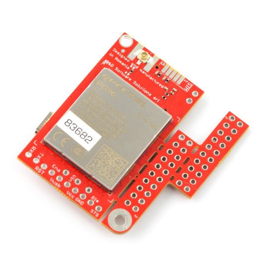
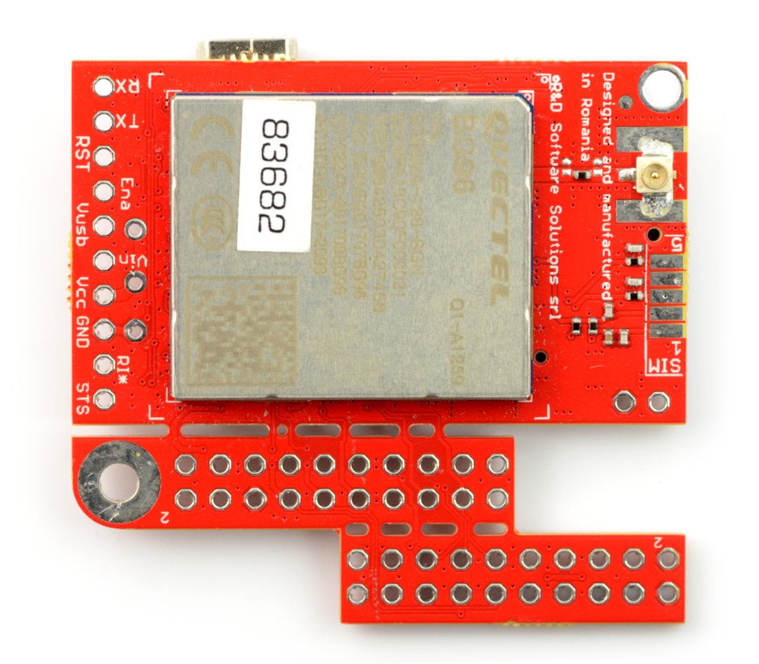
The module working withArduino,Raspberry Pi (version 3B+, 3B, 2B, B+ and A+)andthe BeagleBone Black, which enables communication in the standard of GSM, LTE. It allows forvoice calls, sending SMS messages. The better signal and accuracy is provided bythe GNSS modulewith support forGPS and GLONASS satellites. On the board are: connector forSIM card, powering module for battery LiPol andRESET button. It has connectors ofu.FL antennas for GSM and GNSS. The module supports GNSS antenna - active and passive.
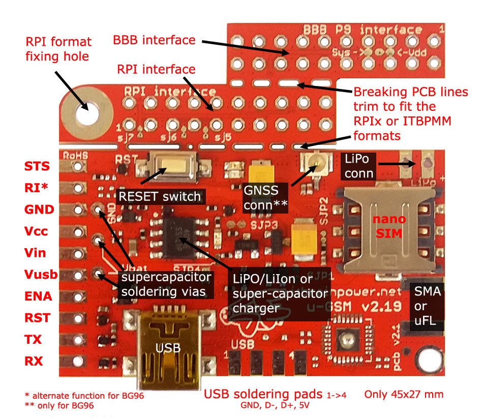
The distribution of elements on the u-uGSM shield board.
Specification
- Driver: Quectel BG96
- Supported standards: GSM / LTE / NB-IoT / EGPRS / GNSS
- Frequency: 800 / 900 / 1800 / 1900 MHz
- FDD LTE: B1 / B2 / B3 / B4 / B5 / B8 / B12 / B13 / B18 / B19 / B20 / B26 / B28
- TDD LTE: B39 (category M1 only)
- Speeds:
- CAT M1: up to max. 300 KB/sec (DL), max. 375 Kbit/s (UL)
- NB-IoT: up to max. 32 Kbit/s (DL), max. 70 Kb/s
- EDGE/GPRS: up to max. 296 Kbit/s (DL), max. 236.8 Kbps (UL) / max. 107 Kbit/s (DL), max 85.6 Kbps (UL)
- GNSS: Galileo, GPS, GLONASS, BeiDou/Compass, QZSS
- Nano SIM / micro SIM connector
- The u.FL antenna connectors
- The built-in USB to UART converter (USB connector can be used to power the module)
- Automatic selection of logic levels from 3 V to 5 V
- The Reset button
- It works withArduino,Raspberry PiandBeagleBone Black, along with sample codes of the manufacturer
- Two mounting holes with the diameter: 2.5 mm
- Board sizes: 45 x 27 mm
|
Detailed module description can be found in the user guide in the firstandsecond part and onthe website of the manufacturer. |
Pins
| Pin | Description |
|---|---|
| STS |
The status pin. |
| RI | The Output Ring Indicator. |
| GND | The ground of the system. |
| VCC | Input/output of 4 V, internally connected to a Li-Pol + pad. |
| VIN | 5 V Input for Li-Pol charger. |
| VUSB | The 5 V output. |
| ENA | The activation pin is activated by the high status. |
| RST | Reset is activated by the high status. |
| TX | Communication is via the serial interface. |
| RX | Communication is via the serial interface. |
The connection to the Arduino
The system works with Arduino Uno using the following pins:
| Pin | Arduino | Description |
|---|---|---|
| GSM RX | D3 | Communication via the serial interface. |
| GSM TX | D2 | Communication via the serial interface. |
| RESET | D6 | System reset of GSM. |
| Ena | D7 | The supply voltage control of the GSM system (On/Off). |
| VIN (5 V LiPol) | 5 V |
Power supply of 5 V. Details of the connection, in case of LiPol battery, are available in the manufacturer's manual. |
|
GND |
GND | The ground of the system. |
|
STATUS |
D5 | The status pin. |
Connection to the Raspberry Pi
The module has special, breakable connectors that allow you to connect directly attached to the GPIO connectors of the Raspberry Pi or BeagleBone Black.
To start the module with the Raspberry Pi, you must perform the following connections:
| Pin | RPi | Description |
|---|---|---|
| GSM RX | 10 |
Communication via the serial interface (not connectedin the USB communication). |
| GSM TX | 08 |
Communication via the serial interface (not connectedin the USB communication). |
| RESET | 18 | System reset of GSM. |
| ON / OFF | 16 | The supply voltage control of the GSM system (On/Off). |
| VIN (5 V LiPol) | 02/04 | The supply voltage of 5 V. |
|
GND |
04/14 | The ground of the system. |
| STATUS | 12 | The status output. |
Useful links |


