Standing rack installation cabinet - 19'' 22U 600x1200mm - black - Lanberg FF01-6022-23B Index: IMP-27399 €412.90 New
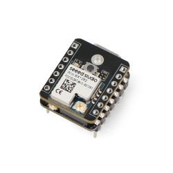
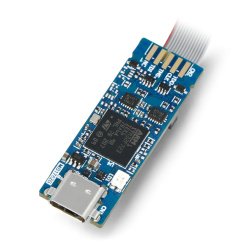
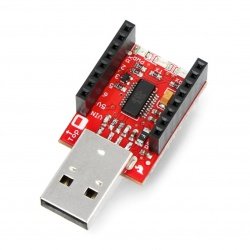
Converter USB-UART FTDI FT232RL 3.3V/5V microUSB - SparkFun BOB-12731 Index: SPF-03090 €35.90 €32.31 Sale Sale
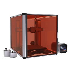
Original Prusa Enclosure - enclosure for 3D printer Index: PSA-23185 €938.50 €844.65 Reduced price Sale
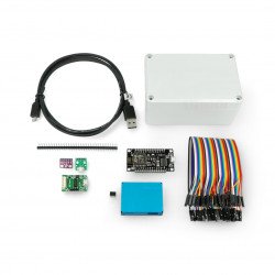
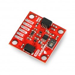
DIY kit for smog sensor - air purity sensor PM2.5 and PM10 Index: SES-13434 €45.90 €41.31 Reduced price Sale
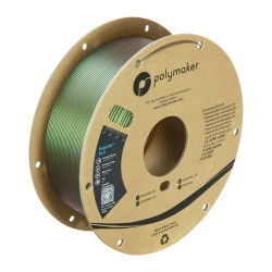
Filament Polymaker Panchroma Starlight PLA 1,75mm 1kg - Meteor Index: PLM-25203 €31.90 €28.71 Reduced price Sale
Inkplate 4 TEMPERA - e-paper display 3,8'' 600x600px - ESP32 - with glass panel -... Index: SOL-24862 €137.50 €116.88 Reduced price Sale
Electric actuator CAR+ 1000N 10mm/s 24V - 40cm stroke Index: ELB-19959 €64.00 €57.60 Reduced price Sale