Product description: Pololu MC33926 - two-channel driver for 28V / 2.5A motors
The module based on the MC33926 system allows you to control two motors with a supply voltage of max. 28 V and a continuous current consumption of up to 3 A (with the use of appropriate cooling). The controller can also withstand a few seconds of current jumps up to 5 A. The rotational speed can be controlled by aPWMsignal up to 20 kHz. The analog FB output allows you to measure the current consumption of the motors with a sensitivity of 0.525 V / A. The module is also protected against the flow of too high current and overheating of the system. Details in thedocumentation.
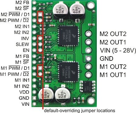
| PIN | Description |
| VIN GND |
Power supply for motors (5V-28V). Mass potential. |
|
M1_OUT1 |
Channel outputs controlled by inputs M1_IN1 and M1_IN2. |
| M1_OUT1 M1_OUT2 |
Channel outputs controlled by inputs M1_IN1 and M1_IN2. |
| PWM / D2 | Blocking input - inverted. When D2 is low, OUT1 and OUT2 are high impedance. PWM input is not inverted. A filling of 70% for the controller also gives 70% for the motor. The output defaults to low. |
| PWM / D1 | Blocking input. When D2 is high, OUT1 and OUT2 are high impedance. PWM input is inverted Giving 70% duty cycle will give the motor 100% -70% or 30%. The output is high by default. |
|
M1_IN1 M1_IN2 |
Inputs controlling the M1_OUT1 and M1_OUT2 outputs. The output is high by default. |
| M2_IN1 M2_IN2 |
Inputs controlling the outputs M2_OUT1 and M2_OUT2. The output is high by default. |
| VDD | 3V-5V voltage output. It is recommended to use only to pull the SF pin high. |
| SF | Status flag for overcurrent or short circuit. Default in high state. In case of problems, the low status appears. The output is high by default. |
|
FB |
An output that allows you to measure the flowing current. The voltage increases by approx. 525mV per 1A. The output defaults to low. |
|
EN |
Sleep state. When low is given, both channels will be in low power mode. The output defaults to low. |
|
SLEW |
Output voltage edge rise time selection. Low state - slow rise (1.5us - 6us). High - fast rise (0.2us - 1.45us). For PWM frequencies above 10kHz, it is recommended to select a fast ramp. The output defaults to low. |
|
INV |
The high state switches the control of inputs IN1 and IN2 for both channels. The output defaults to low. |
Dimensions
The module outline is a rectangle with dimensions of 25.4 x 30.5 mm.
Heat dissipation
The MC33926 integrated circuit, which was used in the module, has a maximum continuous current of 5 A. However, without adequate cooling, the controller will overheat at lower currents. For example, at room temperature, the controlleris able to deliver5 A for about 5 seconds, and 4 A for about 18 seconds. After this time, the temperature protection turned off the system. With a consumption of 3 A, the protection triggered after a few minutes. To increase the current capabilities of the system, a heat sink should be used, which can be mounted with athermally conductive glue.

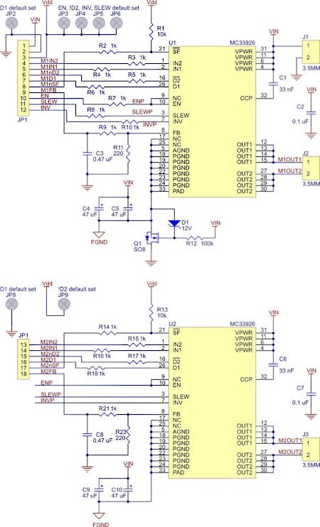
Diagram of the module
The system includes the necessary components for the correct operation of the controller. The conclusions are the popular goldpin connectors (2.54 mm pitch), thanks to which the system can be connected usingwires.
Specification of the driver for Pololu MC33926 motors
- Supply voltage of motors: 5 V - 28 V
- Voltage of logic signals: 2.5 V - 5.5 V
- Continuous output current per channel: 2.5 A
- Maximum instantaneous current per channel: 5 A
- PWM frequency: up to 20 kHz
- Protection against improper connection of the power supply
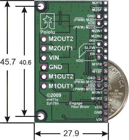
- Dimensions: 45.7 x 27.9 mm
- Weight: 8 g

The set includes: module, power connector, goldpin strip.
Useful links |


